



Selecting between an Inductive/Electromagnetic Potential Transformer (PT) and a Capacitive Voltage Transformer (CVT) is one of the most critical decisions in high-voltage substation engineering.
For medium voltage applications (up to 35kV), cast resin or oil-immersed inductive PTs dominate due to simple construction and low dielectric stress. However, as system voltage reaches 110kV, 220kV, and 500kV, the insulation stack cost for inductive transformers scales exponentially.
How a CVT divides the voltage
A CVT solves this challenge by dividing the line voltage down to an intermediate voltage (typically 10kV to 20kV) using a stack of high-grade paper/polypropylene dielectric capacitor units. The intermediate electromagnetic unit then steps this voltage down to standard 100V or 110V output.
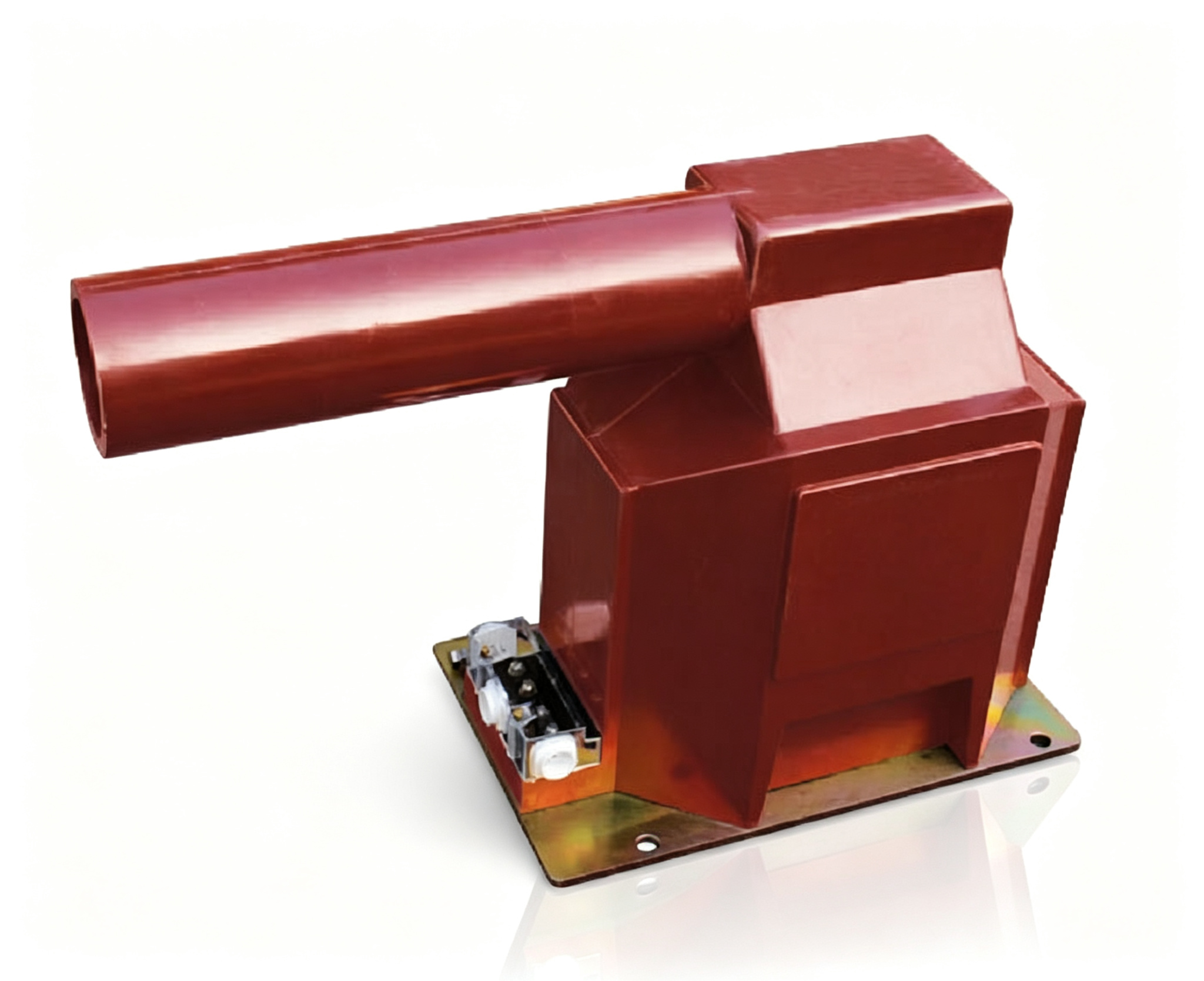
PT vs CVT at a glance
| Criterion | Inductive PT | Capacitive CVT |
|---|---|---|
| Typical system voltage | 0.66–145 kV (cast resin up to 40.5 kV) | 110–765 kV |
| Metering class | 0.1 / 0.2 / 0.5 | 0.2 / 0.5 |
| Transient response | No stored energy; reproduces the primary waveform | Minor transient error during abrupt voltage dips |
| PLC coupling | Not available | 5,000–20,000 pF, doubles as the coupling capacitor |
| Ferroresonance | Possible; damper required | Lower risk; damper still specified |
| Footprint at EHV | Insulation stack grows with voltage | Capacitor stack, still smaller per kV |
| Cost above 138 kV | Rises steeply with voltage | Materially more economical |
Key Comparison Metrics:
1. Accuracy & Transient Response: Inductive PTs deliver standard Class 0.1 and 0.2S accuracy with zero phase delay. CVTs achieve Class 0.2 accuracy for steady-state metering, but exhibit minor transient energy storage during abrupt voltage dips.
2. Power Line Carrier Communication (PLC): CVTs feature high capacitance (typically 5,000pF to 20,000pF), allowing high-frequency carrier signals to be injected directly onto high-voltage transmission lines for protective relaying and voice links.
3. Ferroresonance Risk: Inductive PTs can experience core saturation during line switching or ungrounded fault clearing. Modern PTs and CVTs from PotentialTransformers.com incorporate integrated electronic or passive ferroresonance dampers.
Ferroresonance is a system phenomenon, not a transformer defect: it appears when a saturable core resonates with the capacitance of the network during switching or a single-phase fault. Specify a damper for both technologies, and state in the RFQ whether it is passive (resistor) or electronic.
Selection guidance by voltage level
| Voltage level | Preferred technology | Why |
|---|---|---|
| ≤ 40.5 kV | Cast-resin inductive PT | Simple, compact, low dielectric stress — the CVT has no economic advantage |
| 66–145 kV | Inductive PT (oil or SF6) | Accuracy and transient performance at moderate insulation cost |
| 220–500 kV | CVT | Capacitor stack is cheaper than an insulation stack and doubles as the PLC coupler |
| 765 kV and above | CVT | Insulation cost of an inductive PT becomes prohibitive |
| Laboratory or GIS | SF6 inductive PT | Highest accuracy and a footprint that fits gas-insulated switchgear |
Conclusion: For 110kV and above where line communication is needed, CVTs are the industry standard. For ultra-high precision laboratory metering and compact GIS switchgear, SF6 gas-insulated inductive PTs remain ideal.
Data to request in an RFQ
| Item | Inductive PT | Capacitive CVT |
|---|---|---|
| Rated voltage and voltage factor | Required | Required |
| Accuracy class and burden range | Required | Required |
| Partial-discharge level and test voltage | Required | Required |
| Capacitance and divider ratio | — | Required |
| Damping method | Required | Required |
| Creepage distance / pollution class | Required | Required |
| Type-test certificates | Required | Required |