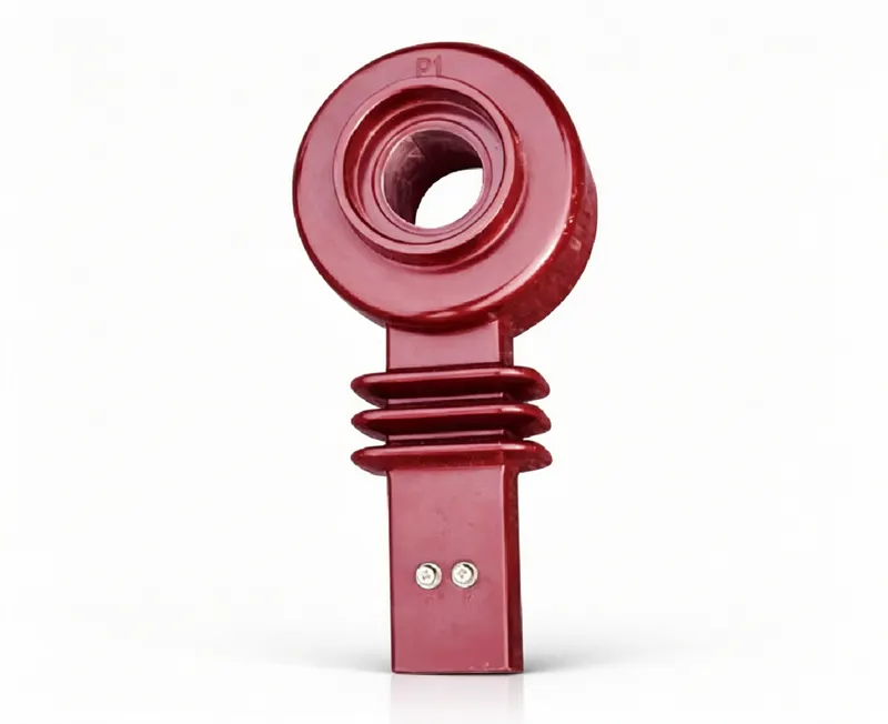
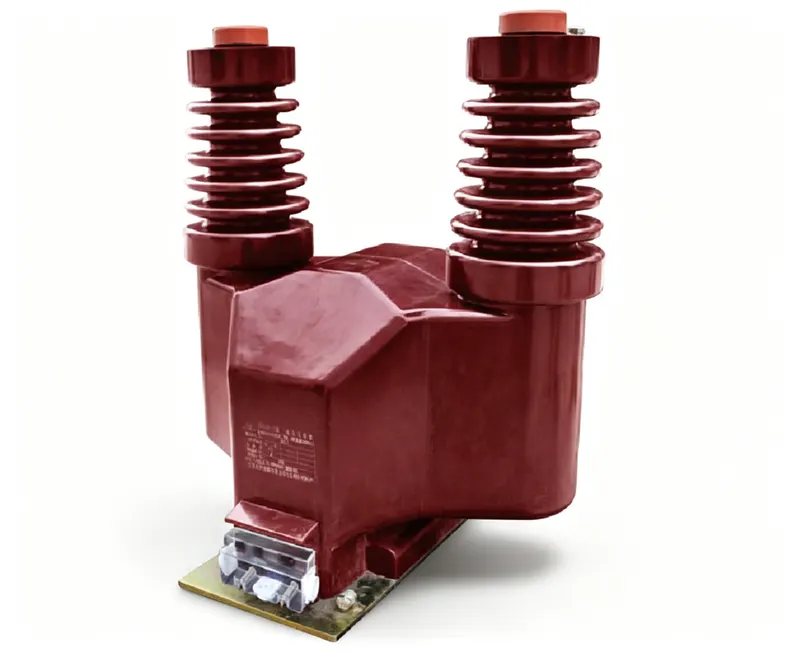
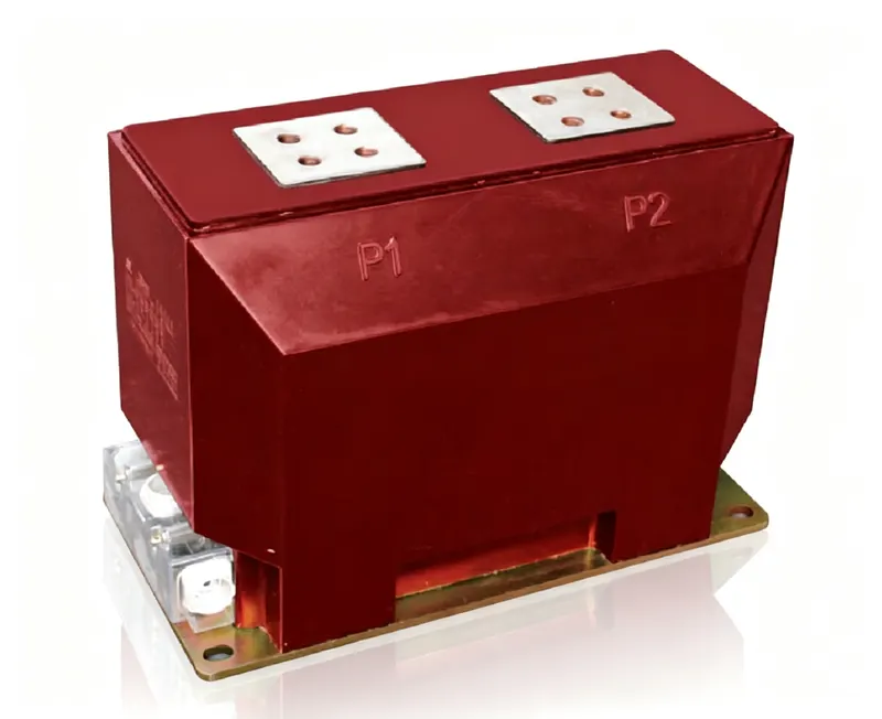
AI data centers are usually described as compute projects: GPUs, networking, storage, cooling. In electrical terms, they are power projects. A single AI hall can draw as much electricity as a small town, and the difference between a good and a bad design is often not the chip count but whether the power chain can measure, protect and control every kilowatt from the utility connection to the rack.
That is where instrument transformers come in. Current transformers (CTs) and voltage transformers (PTs/VTs) are the interface between the high-voltage power system and the low-voltage world of meters, relays, power-quality analysers and control systems. They do not generate or convert power; they produce a scaled, isolated copy of current and voltage that the protection and metering system can use.
This article answers a practical planning question: how many CTs and PTs does an AI data center need? The short answer is that there is no fixed number — it depends on the electrical topology, redundancy, voltage level and how far the design goes into low-voltage monitoring. But a transparent estimate is still useful for budgeting, procurement and early certification planning. This article gives one, with its assumptions clearly stated.
The numbers below are an illustrative planning model for a 100 MW-class campus, not a design document. A real project must be calculated from the single-line diagram, utility requirements, fault levels, protection philosophy and local grid code.
1. The AI power shock in numbers
Traditional enterprise racks typically draw 5–15 kW. AI racks are different. A rack built around eight high-end GPUs can draw 40–60 kW; a rack-scale system such as NVIDIA's GB200 NVL72 is designed around a much higher rack power — on the order of 120 kW — and the next generation is expected to push further. At the campus level, 100 MW is no longer an unusual master plan; multi-hundred-megawatt AI campuses are being announced in several markets.
The demand is visible in the statistics. The International Energy Agency's Energy and AI report estimates data-centre electricity consumption at roughly 415 TWh in 2024, with a pathway towards about 945 TWh by 2030. The Lawrence Berkeley National Laboratory's 2024 United States Data Center Energy Usage Report estimates US data centres at about 176 TWh in 2023 — around 4.4% of US electricity — with a range of 325–580 TWh by 2028 under different AI adoption scenarios. These are estimates, not predictions, but they all point in the same direction: more power, more electrical infrastructure, more measurement points.
For the electrical engineer, three consequences matter:
- Higher power density means more medium-voltage switchgear, more transformer capacity and more feeders in a smaller footprint.
- 2N or N+1 redundancy doubles or multiplies the number of current paths, switchgear bays and therefore CT/PT locations.
- AI load behaviour — fast ramps, low load factors, harmonic-rich power supplies — puts new demands on measurement and protection, not just on cables and cooling.
| Parameter | Traditional enterprise data center | AI data center |
|---|---|---|
| Typical rack density | 5–15 kW | 40–120 kW |
| Annual load factor | Moderate to high | Often low or highly variable during ramp-up |
| Redundancy | N+1 common | 2N common for critical halls |
| Power quality | Mostly linear IT loads | Harmonic-rich PSUs, UPS and rectifiers; DC components possible |
| Cooling | Air-cooled CRAC/CRAH | Liquid cooling, CDUs, chillers and pumps — more motor feeders |
| Electrical uncertainty | Well-understood profiles | Rapidly changing GPU roadmaps and rack power |
2. Why the electrical chain matters
An AI campus is not a single load. It is a chain of conversions and distribution stages, each with its own voltage, fault level, protection philosophy and metering requirement. Figure 1 shows a simplified chain; the numbers are used throughout this article.
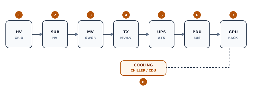
Each stage has a different answer to the question “what do we need to measure?”:
| Stage | Voltage level | What is measured / protected | Typical instrument transformers |
|---|---|---|---|
| Utility | 110–220 kV | Revenue metering, line protection, fault recording | HV CTs and CVTs/PTs, one set per circuit |
| HV substation | 110–220 kV | Busbar protection, transformer differential, breaker failure | HV CTs (multi-core), bus PTs, neutral CTs |
| MV switchgear | 10–35 kV | Incoming, bus tie, transformer and feeder protection; metering | MV CTs, MV PTs, zero-sequence CTs |
| MV/LV TX | 10–35 kV / 0.4–0.69 kV | Transformer differential, overcurrent, temperature | HV/MV CTs on both sides; LV CTs on the secondary |
| UPS / ATS | 0.4–0.69 kV | Input/output current, transfer status, battery monitoring | LV current sensors or LV CTs; not IEC HV instrument transformers |
| PDU | 0.4–0.69 kV | Branch circuit monitoring, energy per rack | LV CTs, Rogowski coils or metering chips |
| GPU rack | 48 V DC or 0.4 kV AC | Rack power, PSU status, power capping | Integrated sensors, not instrument transformers |
The important distinction is between IEC 61869 instrument transformers at HV/MV and low-voltage current sensors at the PDU/rack level. Both measure current, but they are different product categories with different standards, accuracy classes, insulation requirements and cost structures. Mixing them in a single “CT count” is one of the most common estimating mistakes.
2.1 What an instrument transformer actually does
A current transformer is connected in series with the primary conductor. The primary current produces a magnetic flux in the core, and the secondary winding delivers a scaled current — normally 5 A or 1 A — to a meter, relay or transducer. Because the secondary is a current source, it must never be open-circuited while primary current flows: an open secondary can produce a dangerous voltage spike, saturate the core and damage insulation or connected devices. Shorting the secondary is the safe state during testing.
A voltage transformer is connected in parallel with the circuit. Its primary winding sees the system voltage, and its secondary delivers a standard 100 V, 110 V or 100/√3 V signal. Because the secondary behaves like a voltage source, it must never be short-circuited while the primary is energised; a short circuit can draw a large current and damage the winding. The correct safe state is an open secondary, protected by a fuse or miniature circuit breaker.
Both devices provide galvanic isolation and a standardised output, so one meter or relay design can be used at 10 kV, 35 kV or 220 kV. The price of that convenience is a set of accuracy and burden rules: the accuracy class is guaranteed only within a specified burden range, and the protection class is guaranteed only up to a specified accuracy-limit factor. A CT that is correct on paper but outside its burden or ALF window is not a correct CT.
- CT: series connection, current source, secondary must not be open, standard 1 A or 5 A output.
- PT/VT: parallel connection, voltage source, secondary must not be shorted, standard 100 V or 110 V output.
- CVT: a capacitor divider plus an electromagnetic unit, used at higher voltages; its transient behaviour differs from an inductive PT.
- Accuracy class: the error limit at a stated burden and current/voltage range, not a statement about the whole operating envelope.
3. Where CTs and PTs actually sit
Figure 2 shows a simplified single-line diagram with the six most common instrument-transformer locations in an AI campus.
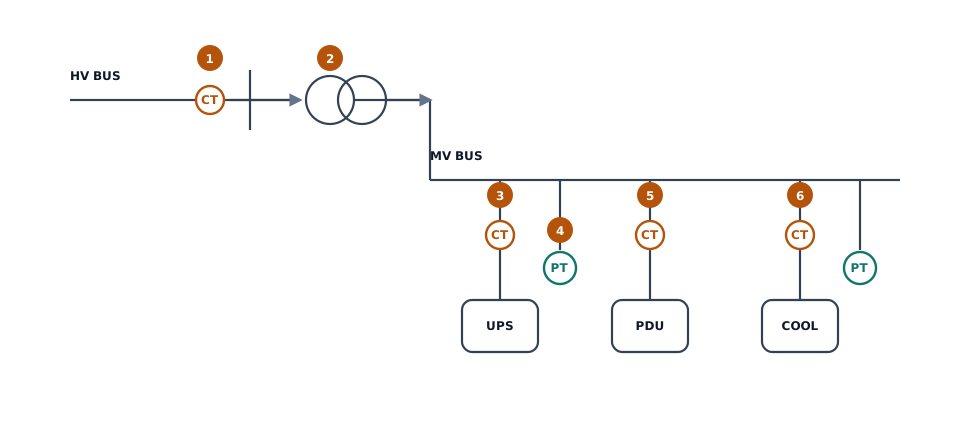
The functions can be grouped into three families:
Metering cores
Revenue metering and energy allocation require accuracy at normal load and, increasingly, at light load. Class 0.2S or 0.5S is common for utility billing and internal cost allocation. The “S” suffix matters in AI campuses because a hall may run at 20–40% of its design load for months during commissioning or between training jobs. A CT specified only for accuracy near rated current can introduce a systematic bias exactly when the campus is lightly loaded.
Protection cores
Protection cores are specified by composite error at the accuracy-limit primary current — for example 5P20 or 5P30. AI campuses have high available fault current and parallel paths, so the accuracy-limit factor (ALF) must be checked against the prospective fault level and the relay setting. A CT that saturates early can slow down or misoperate a protection scheme, even if its nameplate looks adequate.
Neutral and zero-sequence CTs
Earth-fault protection on MV feeders, transformer neutrals and generator/transformer groups needs residual or zero-sequence current measurement. These CTs are often overlooked in early counts because they sit outside the three-phase set, but they are essential for selective earth-fault protection in a 2N architecture.
| Location | Function | Typical class | Typical quantity per bay |
|---|---|---|---|
| HV line / incomer | Revenue metering, line protection, fault recording | 0.2S metering + 5P30/TPY protection | 3 phase CTs, 1 neutral CT, 3 PTs or 1 three-phase unit |
| HV transformer differential | Transformer differential, restricted earth fault | 5P30 or TPS/TPX | 3 CTs per side, 1 neutral CT |
| MV incoming / bus tie | Overcurrent, busbar protection, metering | 0.5/0.2S + 5P30 | 3 CTs, 3 PTs per bus section |
| MV feeder | Overcurrent, earth fault, cable protection | 5P20/5P30 + 0.5/0.2S | 3 CTs, optional zero-sequence CT |
| MV bus PT | Voltage metering, synchronism, undervoltage | 0.2/0.5/3P | 3 single-phase PTs or 1 three-phase unit |
| LV PDU / rack | Branch monitoring, energy allocation | 1.0 or better | 1 LV CT/sensor per circuit |
4. A reference architecture for the estimate
To make the estimate concrete, assume a 100 MW campus with the following characteristics:
- Total facility power: 100 MW at the utility meter.
- PUE: 1.25, so IT load is about 80 MW.
- Redundancy: 2N for the critical power path; each path can carry the full load.
- MV voltage: 10 kV, 50 Hz (35 kV is also common; the method is the same).
- MV switchgear rating: 2,000 A busbars, 25 kA/1 s fault withstand (example only).
- Topology: two independent MV lineups, each with incoming, bus tie, transformer feeders, UPS feeders and cooling/auxiliary feeders.
In this architecture, the number of CTs is driven mainly by the number of bays, not by the total megawatts. A 100 MW campus with 2N redundancy, separate UPS lineups and large cooling plants typically ends up with dozens of MV bays. That is why a simple “MW divided by transformer size” calculation underestimates the instrument-transformer count.
4.1 Scaling up and down
The same method can be applied to smaller and larger campuses, but the result is not linear. A 30 MW edge or enterprise AI site may have 18–24 MV bays; a 300 MW flagship campus may have 120–160, because 2N duplication, bus segmentation and cooling plants multiply the number of feeders faster than the megawatt rating.
| Campus size | MV bays (2N, example) | HV CT/PT | MV CT/PT | Total IEC instrument transformers |
|---|---|---|---|---|
| 30 MW | 18–24 | 9 / 3 | 54–72 / 12–18 | 75–100 |
| 100 MW | 50–70 | 30 / 9 | 150–210 / 36 | 225–285 |
| 300 MW | 120–160 | 60 / 15 | 360–480 / 90 | 525–645 |
The ranges are wide because the bay count depends on the single-line diagram, the number of UPS and cooling feeders, and the owner's redundancy philosophy. For early-stage planning, use the range and add 15–20% for spares and future capacity. For procurement, replace the range with a bay-by-bay count from the approved single-line diagram.
5. How many CTs and PTs? A transparent count
Start with the power balance:
For a given total power and a chosen bay rating, the minimum number of source bays can be estimated as:
where V is the MV line voltage, Ibay is the bay current rating, DF is a diversity factor (typically 0.8–0.9 for a planned campus) and R is the redundancy multiplier (2 for 2N). This gives the minimum number of source bays; the actual bay count is set by the single-line diagram and the number of feeders.
For physical CT units, a three-phase bay normally needs three CTs; a neutral CT is added where earth-fault protection requires it. If each phase has two cores (metering + protection), that is still one physical CT with two cores, not two CTs. The distinction matters for cost and panel space:
where kcore is 1 for a single-core CT and 2 for a dual-core CT if the estimator counts cores instead of physical units. Be explicit about which unit you are counting.
For PTs, the count follows bus sections rather than bays:
for three single-phase PTs per bus section, or one three-phase unit per section if that is the chosen design. HV substations add their own CT/PT sets at the line, bus and transformer bays.
Worked example
Assume the 100 MW campus has 60 MV bays after 2N duplication and functional segmentation, plus 12 MV bus sections. Using three CTs per bay and three single-phase PTs per bus section:
- MV CTs: 60 × 3 = 180 (plus neutral CTs, if every feeder has one)
- MV PTs: 12 × 3 = 36
- HV CTs: 10 circuits × 3 = 30 (plus transformer neutrals)
- HV PTs: 3 bus sections × 3 = 9
- Total IEC instrument transformers: about 255, before spares and future feeders
Adding 10–20% for spares, future capacity and design changes gives a planning range of roughly 280–310 units. A more compact topology with fewer, larger transformers may land near 150–200; a highly segmented 2N design with many small feeders can exceed 400.
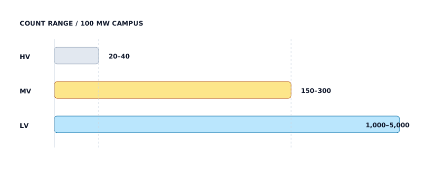
| Scope | Low estimate | Base estimate | High estimate |
|---|---|---|---|
| HV CTs (all cores as physical units) | 18 | 30 | 45 |
| HV PTs / CVTs | 6 | 9 | 12 |
| MV CTs | 120 | 180 | 300 |
| MV PTs | 24 | 36 | 60 |
| IEC instrument transformers | 168 | 255 | 417 |
| LV current sensors / CTs (PDU, rack, UPS) | 1,000 | 2,500 | 5,000 |
5.1 Five common estimation mistakes
- Counting cores as physical CTs. A dual-core CT is one housing with two secondary cores, not two separate devices. It occupies one primary window and one set of insulation, but it requires two sets of secondary wiring and two relay/meter inputs. State the counting unit explicitly in the bill of materials.
- Forgetting neutral and zero-sequence CTs. Earth-fault protection, transformer restricted earth fault and generator/transformer differential schemes need current measurement outside the three phase conductors. These CTs are often missing from early counts and appear late as a cost and space problem.
- Mixing LV sensors with IEC instrument transformers. A rack PDU current sensor and a 10 kV CT are not interchangeable, even if both output a current or a digital signal. They follow different standards, have different accuracy and insulation requirements, and sit in different procurement packages.
- Using transformer MVA alone. The number of CTs is driven by the number of bays, feeders and bus sections, not just the transformer capacity. A campus with many small feeders can have more CTs than a campus with fewer large transformers.
- Forgetting spares, future feeders and testing. A 2N campus is often built with spare bays and future capacity. Add 10–20% for spares, and include the CTs needed for factory and site acceptance testing in the project schedule.
6. Why the count is not the whole story
A count is useful for budgeting, but it says nothing about whether the specified CTs and PTs will actually work. Four technical issues dominate AI-campus designs.
6.1 Low load factor and the 0.2S class
AI halls often run well below design load during commissioning, between jobs, or when only part of the GPU fleet is active. A CT rated for the design current may operate at 20–40% of its primary rating for long periods. At low current, ratio error and phase displacement grow; a conventional 0.5 class may drift outside its guaranteed accuracy. Class 0.2S or 0.5S extends the accuracy range down to 1% of rated current, which is why it is increasingly specified for AI-campus revenue and cost-allocation metering.
6.2 Burden and long secondary runs
The CT accuracy class is only valid up to its rated burden. The secondary loop includes the CT winding, the cable, the relay/meter and the terminals:
and the cable resistance is:
For long runs from a remote MV room to a central control room, a 5 A secondary can consume the entire burden in cable losses. A 1 A secondary reduces the cable burden by a factor of 25 at the same VA, which is why 1 A CTs are common in large campuses and export projects. The trade-off is that 1 A CTs have more turns and can be more expensive; the decision should be made from the actual loop length, not from habit.
6.3 Harmonics and DC components
GPU power supplies, UPS rectifiers and variable-frequency drives inject harmonics. A CT designed for sinusoidal 50/60 Hz accuracy may not reproduce the harmonic content faithfully; power-quality measurement should use a sensor and analyser specified for the harmonic range, not a revenue meter alone. The total harmonic distortion is:
Protection CTs also see DC components during faults and switching. A CT with insufficient core area or incorrect class can saturate and slow the protection. For critical AI-campus feeders, check the transient performance (TPX/TPY/TPS where required) rather than relying only on the 5P class.
6.4 Environment and certification
Indoor MV rooms are cleaner than outdoor substations, but AI campuses add their own requirements: high ambient temperature near UPS rooms, seismic qualification in some regions, low partial discharge for long-life resin insulation, and conformance to local grid codes. In North America, UL/CSA recognition and IEEE C57.13 may be required alongside IEC 61869; in Europe and the Middle East, KEMA or equivalent type-test reports are common. Certification is often the longest lead item — longer than the production of the CT itself.
| Specification item | Recommended for AI campus | Why |
|---|---|---|
| Metering accuracy | 0.2S or 0.5S | Accuracy at 1–120% of rated current; low-load operation |
| Protection class | 5P30 or TPX/TPY where required | High fault levels and DC components |
| Secondary current | 1 A for long runs; 5 A for short runs | Reduce cable burden; match relay/meter inputs |
| Rated burden | Calculate the loop; add 25% margin | Accuracy is only guaranteed up to rated burden |
| Insulation | Low PD, epoxy cast, 12/42/75 kV for 10 kV | Long life, indoor MV switchgear |
| Seismic | Project-specific qualification | Data-center sites in seismic regions |
| Certification | IEC 61869 + UL/CSA or KEMA as required | Utility/EPC acceptance and insurance |
7. What is different about an AI campus?
Five electrical behaviours distinguish AI campuses from conventional enterprise data centers:
- Faster load ramps. A training cluster can move from idle to full power in seconds. Protection must remain stable during inrush and load steps; metering must not lose accuracy during frequent low-load periods.
- Lower average load factor. The campus may be sized for a future GPU generation but run at a fraction of design load for months. This favours extended-range metering classes and wide-range CTs.
- Higher harmonic content. More switched-mode power supplies and UPS rectifiers mean more harmonic current and voltage distortion. Power-quality monitoring becomes a design requirement, not an optional extra.
- More parallel paths. 2N redundancy doubles the number of CTs and PTs and complicates protection coordination. A CT that is adequate in a single path may misoperate when two paths are paralleled.
- Cooling as a major load. Liquid cooling adds chillers, CDUs, pumps and controls — each with its own motor protection and metering requirements.
The digital layer is changing too. Electronic instrument transformers, Rogowski coils, low-power instrument transformers (LPITs) and merging units make it possible to send digitised measurements over IEC 61850 process buses. AI analytics can then use that data for anomaly detection, predictive maintenance and capacity planning. But the analytics are only as good as the sensor: a drifting CT or a saturated protection core will produce confident, wrong conclusions. AI does not replace the instrument transformer; it makes the quality of the instrument transformer more visible.
7.1 From sensor to AI: the data chain
An AI analytics layer does not connect directly to a CT. The signal passes through several stages, and each stage can add error, delay or ambiguity:
- Sensor: CT/PT or LPIT converts the primary quantity into a secondary signal.
- Measurement device: a protection relay, power meter, power-quality analyser or merging unit digitises the signal.
- Control system: SCADA, DCIM or EPMS collects the values, applies scaling and stores time-series data.
- Historian / data platform: normalises timestamps, units and asset identifiers.
- Analytics: anomaly detection, load forecasting, loss analysis, predictive maintenance.
If the CT is 1% low, every downstream calculation inherits that bias. If the relay and the meter use different CT cores with different accuracy classes, their readings will not agree — and an AI model trained on one will look “wrong” when compared with the other. The data chain is therefore an accuracy chain: the weakest link sets the quality of the AI output. This is why AI-campus projects need a metering architecture, not just a list of sensors.
Time synchronisation is the second issue. AI anomaly detection compares events across feeders and floors; if the timestamps are off by tens of milliseconds, the correlation can point to the wrong cause. IEC 61850 process-bus designs should specify time-sync requirements (PTP/IEEE 1588 or GPS) together with the merging-unit accuracy. Cybersecurity is the third: a measurement network that feeds AI also feeds protection and billing, so segmentation, authentication and audit logging are part of the design.
8. Certification and supply chain
Instrument transformers are long-lived, certified components. For an AI campus, the procurement sequence usually looks like this:
| Market | Core standard | Typical evidence | Planning note |
|---|---|---|---|
| Global / IEC | IEC 61869-2 (CT), IEC 61869-3 (PT), IEC 61869-5 (CVT) | Type-test reports, routine test reports | Start certification before the GPU order is final |
| North America | IEEE C57.13, UL/CSA | UL recognition, IEEE type tests | Allow extra time for NRTL review |
| Europe / Middle East | IEC 61869 + local grid code | KEMA or equivalent type tests | Utility approval can take months |
| Data-center EPC | Project specification + IEC | Factory acceptance test, routine tests | Agree on test witness and documentation early |
Because AI campuses are schedule-driven, the CT/PT package is often on the critical path even though it is a small fraction of the electrical budget. Early selection of the topology, accuracy classes and certification route is more valuable than squeezing the unit price.
8.1 Questions to ask a supplier
- Which type tests are available, and to which edition of IEC 61869? Ask for the report number and the test laboratory, not just a certificate cover page.
- What is the accuracy at 1%, 5% and 20% of rated current? A 0.2S claim is only useful if the low-current points are actually tested.
- What is the rated burden, and what is the measured burden of the proposed loop? The class is valid only up to the stated burden.
- What is the ALF and the transient performance? For AI-campus feeders with high fault levels, 5P30 may not be enough; ask for TPX/TPY/TPS evidence where required.
- What is the partial-discharge level and the routine-test regime? Low PD is a long-life indicator for cast-resin insulation.
- Is the product UL/CSA recognised, or does it have KEMA-type reports for the target market? Certification often controls the lead time more than production does.
- What is the seismic qualification? Especially for rooftop or containerised MV rooms in earthquake zones.
- What is the factory acceptance test and documentation package? Agree on witnessed tests, routine-test reports and calibration records before the order.
9. FAQ
How many CTs and PTs does a 100 MW AI data center need?
A planning range is roughly 150–400 IEC instrument transformers (HV + MV), with a base estimate around 250 for a 2N, 10 kV campus with 60 MV bays. Add 1,000–5,000 low-voltage current sensors if the scope includes PDU and rack-level monitoring.
Are low-voltage CTs in PDUs the same as instrument transformers?
No. They measure current, but they are low-voltage sensors with different standards, insulation and accuracy requirements. Keep them in a separate budget line and a separate count.
Should I use 1 A or 5 A secondary?
Use 1 A when the secondary run is long or the burden is tight; use 5 A for short runs where standard relays and meters are designed around 5 A. Calculate the loop burden before deciding; do not choose by habit.
Is 0.2S necessary if the campus will run at full load?
If the load truly stays near design current, 0.5 may be sufficient. In practice, AI campuses spend significant time at low load during commissioning and between jobs, so 0.2S is often justified for revenue and cost-allocation metering.
Can AI monitor the CTs and PTs themselves?
AI can detect trends and anomalies from online monitoring data — temperature, partial discharge, secondary burden, ratio drift — but it does not replace routine tests, calibration or protection coordination. It adds a layer of condition monitoring, not a substitute for type tests.
10. Conclusion
The number of instrument transformers in an AI data center is not a single number; it is a function of topology, redundancy, voltage level and scope. A 100 MW campus can reasonably carry 150–400 HV/MV CTs and PTs, plus thousands of low-voltage sensors if rack-level monitoring is included. The more important questions are where those devices sit, what accuracy and protection classes they need, and whether the chosen supplier can deliver certified products on the project schedule.
AI is often described as a compute revolution. Electrically, it is also a measurement and protection problem. The campuses that run reliably will be the ones that treat the CTs and PTs not as commodity accessories, but as part of the power chain’s nervous system.
9.1 Where to go next
For the MV switchgear side, typical cast-resin CTs include the LZZBJ9-10GWA,B,C and the busbar-type LMZ9-10. For voltage measurement, the JDZ10-35R is a 35 kV indoor inductive PT. If you are still choosing between a CVT and an inductive PT, read PT vs CVT: selection guide; for the standard background, see IEC 61869-3 explained.
References
- International Energy Agency (IEA). Energy and AI. 2025. https://www.iea.org/reports/energy-and-ai
- Lawrence Berkeley National Laboratory. 2024 United States Data Center Energy Usage Report. 2024. https://eta-publications.lbl.gov/publications/2024-lbnl-data-center-energy-usage-report
- Uptime Institute. 2024 Global Data Center Survey. 2024. https://datacenter.uptimeinstitute.com/rs/711-RIA-145/images/2024.GlobalDataCenterSurvey.Report.pdf
- Electric Power Research Institute (EPRI). Powering Intelligence: Updated Scenarios of U.S. Data Center Electricity Use and Power Strategies. 2026. https://esca.epri.com/products/3002034697/
- ASHRAE. AI Data Center: Integrated Design Principles. https://www.ashrae.org/technical-resources/topics-and-initiatives/ai-data-center/integrated-design-principles
- IEC 61869-2:2012. Instrument transformers — Part 2: Additional requirements for current transformers.
- IEC 61869-3:2011. Instrument transformers — Part 3: Additional requirements for inductive voltage transformers.
- IEC 61869-5:2011. Instrument transformers — Part 5: Additional requirements for capacitor voltage transformers.
- IEEE C57.13-2016. IEEE Standard Requirements for Instrument Transformers. https://standards.ieee.org/ieee/829/4867/
- Schneider Electric. AI Factory: Design, simulate, build, operate and maintain high-density AI infrastructure. https://www.se.com/us/en/work/solutions/ai-factory/
- NVIDIA. GB200 NVL72. https://www.nvidia.com/en-us/data-center/gb200-nvl72/
- Electrical Engineering Portal. Instrument Current and Voltage Transformers (course PDF). https://electrical-engineering-portal.com/res/Instrument-Current-and-Voltage-Transformers-2.pdf
- U.S. Department of Energy. Data Center Energy Efficiency. https://www.energy.gov/eere/buildings/data-center-energy-efficiency
The count ranges and the 100 MW example are the author's planning model, built from the references above and typical MV switchgear topologies. They are not a substitute for a project-specific single-line diagram, protection study or bill of materials.