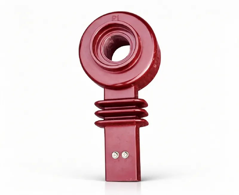
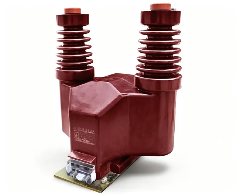
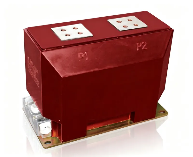
An AI data center is often drawn as a single-line diagram: a utility connection, a substation, medium-voltage switchgear, transformers, UPS systems, PDUs and racks. That drawing hides the fact that the power chain crosses several electrical domains. Each domain has a different voltage, fault level, grounding system, protection philosophy and accuracy requirement — and therefore a different answer to the question “which CT or PT belongs here?”
This article walks the chain from the 110 kV connection to the GPU rack and explains what is measured at each stage, which instrument transformer type is appropriate, and where the common design mistakes occur. It is a companion to the planning model in How many instrument transformers does an AI data center need?; that article estimates the quantity, while this one explains the selection.
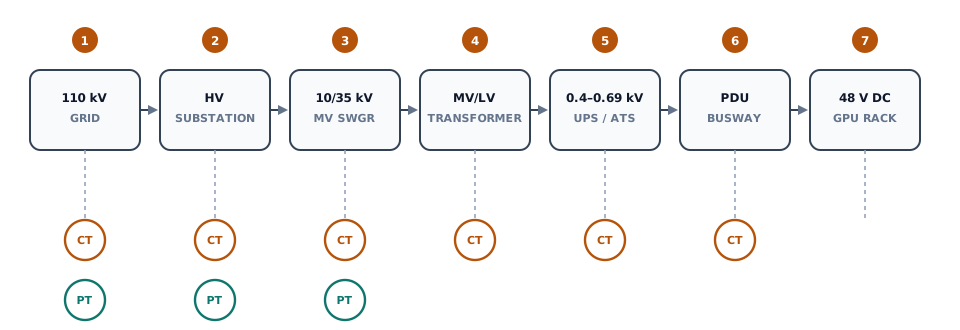
1. The chain is a set of voltage domains
The first design decision is not “which CT ratio?” but “where are the protection and metering boundaries?” A CT is not a generic current sensor that can be moved anywhere; its location defines the protection zone, the fault current it must withstand and the burden it must drive. A PT is not a generic voltage tap; its location defines whether it measures bus voltage, line voltage or a residual voltage.
Figure 1 shows the seven stages used in this article, with the measurement layer separated from the power path.
| Stage | Voltage | Primary equipment | Main measurement / protection | Instrument transformer family |
|---|---|---|---|---|
| 1. Grid | 110–220 kV | Transmission line, metering point | Revenue metering, line protection, fault recording | HV CTs + CVTs or inductive PTs |
| 2. HV sub | 110–220 kV | Busbars, breakers, HV/MV transformers | Busbar protection, transformer differential, breaker failure | HV CTs, bus PTs, neutral CTs |
| 3. MV swgr | 10–35 kV | Incoming, bus tie, feeders | Overcurrent, earth fault, metering, sync check | MV CTs, MV PTs, zero-sequence CTs |
| 4. TX | 10–35 kV / 0.4–0.69 kV | Distribution transformer | Differential, overcurrent, temperature | MV and LV CTs; no PT on the LV side in most designs |
| 5. UPS | 0.4–0.69 kV | UPS, static transfer switch, generator breaker | Input/output current, transfer, battery monitoring | LV CTs or current sensors |
| 6. PDU | 0.4–0.69 kV | Power distribution units, busway | Branch energy, overload, load balancing | LV CTs, Rogowski coils, metering chips |
| 7. GPU | 48 V DC or 0.4 kV AC | Server PSUs, rack power shelf | Rack power, power capping, PSU status | Integrated sensors, not IEC instrument transformers |
2. Stage 1–2: the 110 kV connection and HV substation
At 110 kV or 220 kV, the instrument transformers are part of the utility interface. The utility usually owns the revenue metering, but the data-center owner still needs its own check meters, protection CTs and fault recording. This is why a single HV circuit may carry several CT cores: one or two metering cores (0.2S or 0.5S), one or two protection cores (5P30, TPX/TPY or TPS), and sometimes a separate core for fault recording or power quality.
The voltage measurement at this level is usually a CVT or an inductive PT. A CVT uses a capacitor divider (C1/C2) followed by a compensation reactor and an intermediate transformer; it is compact and economical at extra-high voltage, but its transient response and ferroresonance behaviour differ from an inductive PT. An inductive PT is simpler and has better transient behaviour, but becomes large and expensive at 220 kV and above. The choice is not only a price decision; it affects protection performance during voltage dips and switching events.
Inside the HV substation, the key CT locations are:
- Line-side CTs for line protection and revenue metering, at the boundary between utility and customer.
- Busbar CTs for busbar differential protection, one set per incoming and outgoing circuit.
- Transformer HV and MV CTs for transformer differential protection; the two sets must be coordinated so that the differential relay sees the transformer, not the busbar.
- Neutral CTs for restricted earth fault and standby earth fault protection.
2.1 CVT or inductive PT?
The voltage transformer choice at 110–220 kV is a system decision, not a catalogue decision. An inductive PT is a conventional transformer: its primary winding is connected phase-to-earth, and its secondary delivers a scaled voltage. It has a predictable transient response and is easy to test, but at 220 kV the insulation and magnetic circuit make it large and expensive.
A CVT uses a capacitor divider to bring the voltage down to an intermediate level, then an electromagnetic unit to produce the secondary output. The capacitor stack is compact and can be designed for very high voltage, but the divider introduces a frequency-dependent network. During a voltage dip, a switching surge or a ferroresonance event, the CVT output may not follow the primary voltage instantaneously. Protection that depends on voltage magnitude or phase angle must account for this behaviour.
For revenue metering, both types can meet 0.2 class if specified and calibrated correctly. For protection, the CVT's transient response and the inductive PT's saturation behaviour are different failure modes. The specification should state the protection functions, the required transient response and the ferroresonance damping, not only the ratio and burden.
At this level, a common mistake is to specify a single “metering and protection” CT with one core. The meter and the relay have different accuracy and burden requirements; sharing one core forces a compromise that satisfies neither. Multi-core CTs cost more than a single-core unit, but they avoid a design that is neither accurate nor stable.
3. Stage 3: MV switchgear from 10 kV to 35 kV
The MV switchgear is where most of the instrument-transformer count sits. A typical AI campus has dozens of MV bays: incoming, bus tie, transformer feeders, UPS feeders, cooling/auxiliary feeders and spare bays. Each bay has a different protection function, and therefore a different CT requirement.
Three families of CT are common:
- Cast-resin CTs around the primary conductor or cable, with one or more cores. These are the standard choice for indoor MV switchgear.
- Busbar-type CTs (window or bar primary) for compact panels and high-current busbars.
- Zero-sequence CTs around the three phases, used for sensitive earth-fault protection. They are not three separate phase CTs; they are a single core encircling all phases.
| CT type | Construction | Typical location | Design note |
|---|---|---|---|
| Cast-resin ring CT | Epoxy-cast ring around cable or bar | MV feeder, incoming, transformer bay | Low PD, high mechanical strength, indoor use |
| Busbar / window CT | Window or bar primary, removable | Main busbar, high-current feeder | Check window size and bar spacing |
| Zero-sequence CT | Large core around all three phases | Feeder cable, transformer neutral | Low ratio, sensitive earth-fault protection |
| Split-core CT | Two-part core for retrofit | Existing cable, temporary monitoring | Lower accuracy; check air-gap effect |
The CT ratio is selected from the rated current, not from the fault current. The fault current determines the accuracy-limit factor and the short-time withstand; the rated current determines the ratio. A 2,000 A bay with a 25 kA fault level needs a CT that can carry 2,000 A continuously and remain accurate up to the protection setting, not a CT sized only for the load.
The ratio follows the turns:
3.1 Core selection: metering, protection and differential
A single physical CT can contain several cores, but each core is a separate design. The metering core is optimised for accuracy at low and normal current; the protection core is optimised for stability at high fault current; the differential core is optimised for matching the other side of the transformer. They may share a housing, but they do not share a specification.
For a typical MV feeder, the bill of materials may look like this:
- Core 1 — metering: 0.2S or 0.5S, rated burden matched to the meter, accuracy checked at 1%, 5% and 20% of rated current.
- Core 2 — overcurrent: 5P20 or 5P30, ALF checked against the prospective fault current, short-time withstand checked against the switchgear rating.
- Core 3 — earth fault: a low-ratio core or a separate zero-sequence CT, sensitive to the expected earth-fault current.
For a transformer differential, the two sides may have different ratios and vector groups. The CTs must be selected so that the relay can compensate for the transformer ratio, and the CT ratio must not be so high that the differential current at low load disappears into the measurement error. This is a protection study task, not a catalogue selection.
The VT at this level is usually a single-phase unit per phase, or a three-phase unit in a common housing. It supplies the relay voltage inputs, the sync-check function and the meter. In a 2N architecture, each bus section needs its own VT so that the protection can still measure voltage when one section is isolated.
4. Stage 4: the MV/LV transformer
The MV/LV transformer is the boundary between the utility-style MV protection and the low-voltage world of the data hall. The transformer differential protection needs CTs on both sides; the CT ratios must compensate for the transformer ratio and the vector group. The LV-side CTs are often mounted in the transformer secondary compartment or in the main LV switchboard.
This is also where the neutral CT becomes important. A transformer with a grounded secondary neutral needs a neutral CT for earth-fault protection and metering. If the neutral is resistively grounded, the CT ratio must match the expected earth-fault current, which may be only tens of amps — not the thousands of amps of a phase fault.
4.1 Vector group and CT matching
The transformer vector group determines the phase shift between the HV and LV sides. A Dyn11 transformer, for example, introduces a 30° shift. The differential relay must compensate for this shift, and the CT ratios on both sides must be selected so that the relay sees the same per-unit current at rated load. If the CTs are mismatched, the relay may see a differential current at normal load and either trip unnecessarily or be desensitised.
The CT ratio on each side is usually chosen from the transformer rated current, not from the switchgear rating. On the LV side, the CT may be mounted in the transformer secondary compartment; on the HV side, it may be a ring CT around the cable. The two CTs can have different accuracy classes, but their ratio and polarity must be coordinated with the relay settings.
A common specification error is to use the same CT class for the phase and neutral CTs. The phase CT may be a 5P30 protection core; the neutral CT may need a much lower ratio and a different class to detect a small earth-fault current. The two functions should be specified separately.
5. Stage 5–7: UPS, PDU and the GPU rack
Below the MV/LV transformer, the voltage is 0.4–0.69 kV AC. This is still a power-distribution domain, but it is no longer an IEC HV instrument-transformer domain. The devices are low-voltage CTs, Rogowski coils, Hall-effect sensors or metering chips. They measure the same physical quantity, but they are not interchangeable with MV CTs.
The UPS/ATS stage needs current measurement on the input, output and bypass paths, plus battery monitoring. The PDU/busway stage needs branch-circuit monitoring for energy allocation and overload detection. The rack stage needs power measurement at the PSU or rack power shelf, often at 48 V DC. At 48 V DC, a conventional AC CT does not work; the sensor must be DC-capable, or the measurement must be derived from the PSU telemetry.
This is why a single “CT count” can be misleading. A 100 MW campus may have 200–300 HV/MV instrument transformers and thousands of low-voltage sensors. They belong in different budget lines, different specifications and different test regimes.
5.1 Why a 10 kV CT cannot be used at the PDU
It is tempting to think that a CT is a CT: it measures current, so a spare 10 kV ring CT should work at 400 V. It does not. The insulation level, the window size, the ratio, the burden and the accuracy class are all wrong for a low-voltage circuit. A 10 kV CT with a 600/5 ratio may have a large core and a high burden; at 400 V it may not resolve a 20 A branch current accurately, and its insulation is unnecessary and expensive.
At the PDU, the correct device is a low-voltage CT, a Rogowski coil or a metering chip designed for the branch current and the available space. The measurement may be 1% or 2% accuracy, which is adequate for energy allocation but not for revenue metering. The test regime is also different: a low-voltage sensor is tested with the PDU, not with the MV switchgear.
6. Protection coordination across the chain
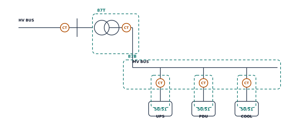
Protection is organised in zones. Each zone is bounded by CTs, and the CTs must overlap so that no fault is left unmeasured. Figure 2 shows the three main zones in an AI campus: transformer differential (87T), busbar differential (87B) and feeder overcurrent/earth fault (50/51, 50N/51N).
The most important CT parameter for protection is not the ratio but the accuracy-limit factor. The CT must remain within its composite error up to the maximum fault current it will see, including the DC offset. The accuracy-limit primary current is:
For example, a 600/1 CT with a 5P20 class has an accuracy-limit primary current of 12 kA. If the prospective fault current is 25 kA, the CT will saturate before the fault current reaches its peak, and the relay may slow down or fail to operate. A 5P40 or 5P50 core, or a TPX/TPY core with a defined transient performance, may be required.
The DC component makes this worse. During the first cycles of a fault, the current is offset; a CT with a small core can saturate even when the symmetrical fault current is within its ALF. For critical AI-campus feeders, ask for the transient performance and the remanence behaviour, not only the 5P class.
6.1 A saturation example
Consider a 600/1 CT with a 5P20 class on a feeder with a 25 kA prospective fault current. The accuracy-limit primary current is 20 × 600 = 12 kA. The fault current is more than twice the ALF, so the CT will saturate during the fault. The relay may still trip, but the fault current measurement will be wrong, and the coordination with upstream protection may be lost.
A 5P50 core would give 30 kA, which covers the symmetrical fault current with margin. If the fault current has a significant DC offset, the required core may be larger still, or a TPX/TPY core with a defined transient performance may be needed. The correct answer comes from the fault study and the relay settings, not from a rule of thumb.
| Protection function | CT location | Typical class | Key check |
|---|---|---|---|
| Transformer differential (87T) | HV and MV sides, plus neutral | 5P30, TPS/TPX or TPY | Ratio compensation, vector group, CT matching |
| Busbar differential (87B) | All incomers and outgoing feeders | 5P30 or TPS | CT ratio consistency, saturation, zone overlap |
| Feeder overcurrent (50/51) | Feeder phase CTs | 5P20/5P30 | ALF versus prospective fault current |
| Earth fault (50N/51N) | Neutral or core-balance CT | 5P10/5P20 or sensitive core-balance | Low fault current, ratio, residual connection |
| Metering / revenue | Line or feeder CTs | 0.2S/0.5S | Burden, low-load accuracy, calibration |
7. Accuracy, burden and the 1 A versus 5 A decision
A CT is a current source; its accuracy is guaranteed only within a specified burden. The secondary loop includes the CT winding, the cable, the relay/meter and the terminals:
The cable resistance is:
This is why the 1 A versus 5 A decision matters. At the same VA, a 1 A secondary reduces the cable loss by a factor of 25. For a long run from a remote MV room to a central control room, a 5 A CT may consume its entire burden in the cable; a 1 A CT leaves more margin for the relay and meter.
| Secondary current | Advantages | Disadvantages | Typical use |
|---|---|---|---|
| 5 A | Standard relays and meters; fewer turns; lower CT cost | Higher cable burden; shorter runs | Compact MV switchgear, short cable runs |
| 1 A | Lower cable burden; longer runs; better for large campuses | More turns; larger CT; higher cost | Remote MV rooms, large AI campuses, export projects |
The VT side has a similar burden question. A CVT has a capacitor divider and an electromagnetic unit; the intermediate voltage is set by the divider:
If C1 or C2 changes with temperature, moisture or a failed element, the secondary voltage changes even when the ratio on the nameplate is correct. This is why capacitance and tan delta tests remain important, and why a CVT fault can pass a low-voltage ratio test.
| Class | Typical application | Accuracy at low load | Notes |
|---|---|---|---|
| 0.2S | Revenue metering, tenant billing | Specified down to 1% of rated current | Preferred for AI campuses with long low-load periods |
| 0.5S | Internal cost allocation, check metering | Specified down to 1% | Good compromise when revenue accuracy is not required |
| 0.5 | General metering | Accuracy guaranteed from a higher current | May drift at low load; check the actual burden |
| 5P20/5P30 | Overcurrent protection | Not applicable | Check ALF against prospective fault current |
| TPX/TPY/TPS | Differential and critical protection | Not applicable | Specify transient performance and remanence |
8. The digital signal chain
In a conventional design, each CT/PT is wired to a relay or meter, and the relay or meter sends data to SCADA. In a digital substation, the CT/PT may feed a merging unit, which publishes sampled values over IEC 61850-9-2. The protection relay subscribes to those values, and the SCADA/DCIM system receives the same data through the process bus or the station bus.
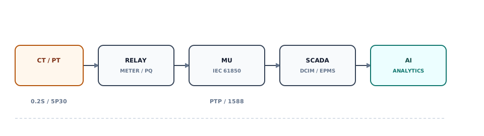
Digitalisation does not remove the need for correct CT/PT selection. It makes the selection more visible: a merging unit with a 0.1% accuracy class cannot compensate for a CT that is outside its burden, and a time-synchronisation error of a few milliseconds can make a perfectly accurate measurement useless for event correlation. The accuracy chain and the time-sync chain must be designed together.
8.1 LPIT and merging units
A low-power instrument transformer (LPIT) is not simply a smaller CT. It produces a low-voltage output — often a few volts or a digital signal — and is specified under IEC 61869-6. Because the output is low, the secondary wiring burden is much less critical, but the sensor needs a local power supply or a merging unit, and its accuracy may depend on temperature and ageing.
The merging unit samples the LPIT outputs and publishes them over IEC 61850-9-2. It also provides the time stamp for each sample. The accuracy of the merging unit and the stability of the time base are part of the measurement chain; a 0.1% merging unit with a 1 ms time error is not a 0.1% measurement system for event correlation. For protection, the merging unit must meet the latency and synchronisation requirements of the relay, not just the accuracy class.
9. Commissioning and factory acceptance
Instrument transformers are routine-tested at the factory and commissioned on site. For an AI campus, the test plan should include:
| Test | Factory | Site | What it catches |
|---|---|---|---|
| Ratio and polarity | Yes | Yes | Wiring errors, reversed cores |
| Insulation resistance / withstand | Yes | Yes | Insulation damage, moisture |
| Excitation / saturation | Yes | Optional | Core defects, wrong class |
| Burden measurement | Yes | Yes | Actual loop burden versus nameplate |
| Partial discharge | Yes | Optional | Insulation defects in cast resin |
| Secondary wiring / trip test | No | Yes | Open circuits, wrong CT polarity, relay settings |
9.1 Site test sequence
A practical sequence for an AI campus is: visual inspection and nameplate check, insulation resistance, ratio and polarity, burden measurement, secondary wiring continuity, relay settings and trip test. The order matters: a ratio test before the wiring check may pass at the CT terminals but fail at the relay because the cable is landed on the wrong core.
For digital substations, add the merging-unit test: sample quality, time-sync status, network latency and the relay's subscription to the correct data stream. A merging unit that publishes the right values but the wrong timestamp is worse than a conventional CT, because the error is invisible to the meter but visible to the event log.
The most common site error is not a failed CT; it is a wiring error. A reversed polarity, an open secondary, a shorted test block or a wrong ratio tap can make a healthy CT look faulty. The commissioning plan should include a point-to-point check of every core and a trip test of every protection function.
10. FAQ
Can one CT serve both metering and protection?
It can have two cores in one housing, but the metering and protection cores should be specified separately. A single core cannot simultaneously optimise low-load accuracy and high-fault stability.
Why use a CVT instead of an inductive PT at 220 kV?
A CVT is more compact and economical at extra-high voltage because the capacitor divider shares the voltage stress. The trade-off is a more complex transient response and the need for ferroresonance damping.
Is a 5P30 CT always enough for an AI campus?
No. Check the prospective fault current and the DC component. A 5P30 CT with a 600/1 ratio has an ALF of 18 kA; if the fault level is 25 kA, it may saturate. Use a higher ALF or a transient-performance class where required.
Do I need a PT on every MV bus section?
In a 2N architecture, yes — each section should have its own voltage source so that protection and sync-check functions remain available when the other section is isolated.
Are low-voltage CTs in PDUs part of the instrument transformer package?
No. They are low-voltage sensors with different standards, insulation and accuracy requirements. Keep them in a separate specification and budget line.
11. Conclusion
The journey from 110 kV to the GPU is a journey through several measurement domains. HV CTs and CVTs define the utility interface; MV CTs and PTs define the protection zones; LV CTs and sensors define the data-hall energy picture. The instruments change, but the principle does not: every protection zone needs a defined boundary, every meter needs a defined burden, and every digital signal needs a defined accuracy and time base.
For the quantity side, see the 100 MW planning model. For product examples, see the LZZBJ9-10GWA,B,C MV CT, the LMZ9-10 busbar CT and the JDZ10-35R indoor PT. For the CVT versus PT trade-off, read the selection guide.
References
- IEC 61869-2:2012. Instrument transformers — Part 2: Additional requirements for current transformers.
- IEC 61869-3:2011. Instrument transformers — Part 3: Additional requirements for inductive voltage transformers.
- IEC 61869-5:2011. Instrument transformers — Part 5: Additional requirements for capacitor voltage transformers.
- IEC 61869-6:2016. Instrument transformers — Part 6: Additional general requirements for low-power instrument transformers.
- IEC 61869-9:2016. Instrument transformers — Part 9: Digital interface for instrument transformers.
- IEC 61850-9-2:2011. Communication networks and systems for power utility automation — Part 9-2: Sampled values over ISO/IEC 8802-3.
- IEEE C57.13-2016. IEEE Standard Requirements for Instrument Transformers. https://standards.ieee.org/ieee/829/4867/
- IEEE C37.110-2007. IEEE Guide for the Application of Current Transformers Used for Protective Relaying Purposes.
- IEEE C37.91-2021. IEEE Guide for Protective Relay Applications to Power Transformers.
- Electrical Engineering Portal. Instrument Current and Voltage Transformers (course PDF). https://electrical-engineering-portal.com/res/Instrument-Current-and-Voltage-Transformers-2.pdf
- International Energy Agency (IEA). Energy and AI. 2025. https://www.iea.org/reports/energy-and-ai
- Lawrence Berkeley National Laboratory. 2024 United States Data Center Energy Usage Report. 2024. https://eta-publications.lbl.gov/publications/2024-lbnl-data-center-energy-usage-report
- Schneider Electric. AI Factory: Design, simulate, build, operate and maintain high-density AI infrastructure. https://www.se.com/us/en/work/solutions/ai-factory/
- NVIDIA. GB200 NVL72. https://www.nvidia.com/en-us/data-center/gb200-nvl72/
The stage descriptions and CT/PT recommendations are a design guide, not a substitute for a project-specific single-line diagram, protection study, CT burden calculation and local grid-code review.