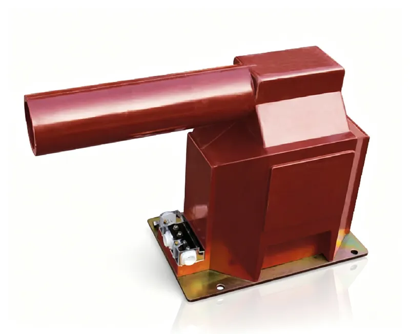
The International Electrotechnical Commission standard IEC 61869-3 establishes global specifications for inductive voltage transformers used in electrical measurement and protection systems.
It is the part of the IEC 61869 family that replaced IEC 60044-2. An engineer specifying a voltage transformer for a project outside China should quote it directly — GB/T 20840.3 is aligned with it, so a unit type-tested to one is normally acceptable under the other.
IEC 61869-3 fixes accuracy, burden and insulation / partial-discharge requirements. A quotation that lists only the accuracy class is incomplete: always ask for the rated burden window, the voltage factor and the partial-discharge level as well.
When specifying potential transformers for international utility projects, engineering firms must pay close attention to three core parameters:
1. Rated Burden & Accuracy Class: Burden represents the total apparent power (VA) connected to the secondary winding. Operating a Class 0.2 PT outside its specified burden window (e.g. 25% to 100% of rated VA) will cause ratio error drift beyond class limits.
The classes that can appear on an inductive VT nameplate, and the limits they stand for:
| Class | Typical application | Ratio error at 80–120% Un | Phase displacement |
|---|---|---|---|
| 0.1 | Laboratory and reference metering | ±0.1% | ±5 min |
| 0.2 | Revenue metering | ±0.2% | ±10 min |
| 0.5 | Commercial and industrial metering | ±0.5% | ±20 min |
| 1.0 | Indication only | ±1.0% | ±40 min |
| 3P | Protection | ±3% at rated voltage factor | Not specified |
| 6P | Protection | ±6% at rated voltage factor | Not specified |
The S suffix (0.2S, 0.5S) belongs to current transformers, defined in IEC 61869-2, where accuracy must hold down to 1% of rated current. Inductive voltage transformers have no S class; the same intent is expressed by Class 0.2 plus the burden range over which it has to hold.
2. Voltage Factor (Vf) & Duration: For effectively grounded systems, the voltage factor is typically 1.2 continuous and 1.5 for 30 seconds. For ungrounded or resonant grounded networks, a voltage factor of 1.9 Un for 8 hours is required to survive ground faults.
| System earthing | Continuous | Fault condition | Duration |
|---|---|---|---|
| Effectively (solidly) earthed | 1.2 Un | 1.5 Un | 30 s |
| Non-effectively earthed / resonant earthed | 1.2 Un | 1.9 Un | 8 h |
3. Partial Discharge (PD) Testing: PD in cast resin or paper-oil insulation indicates microscopic void formation. PotentialTransformers.com tests 100% of production units in our high-voltage Faraday cage, guaranteeing PD < 5pC at 1.2 Un.
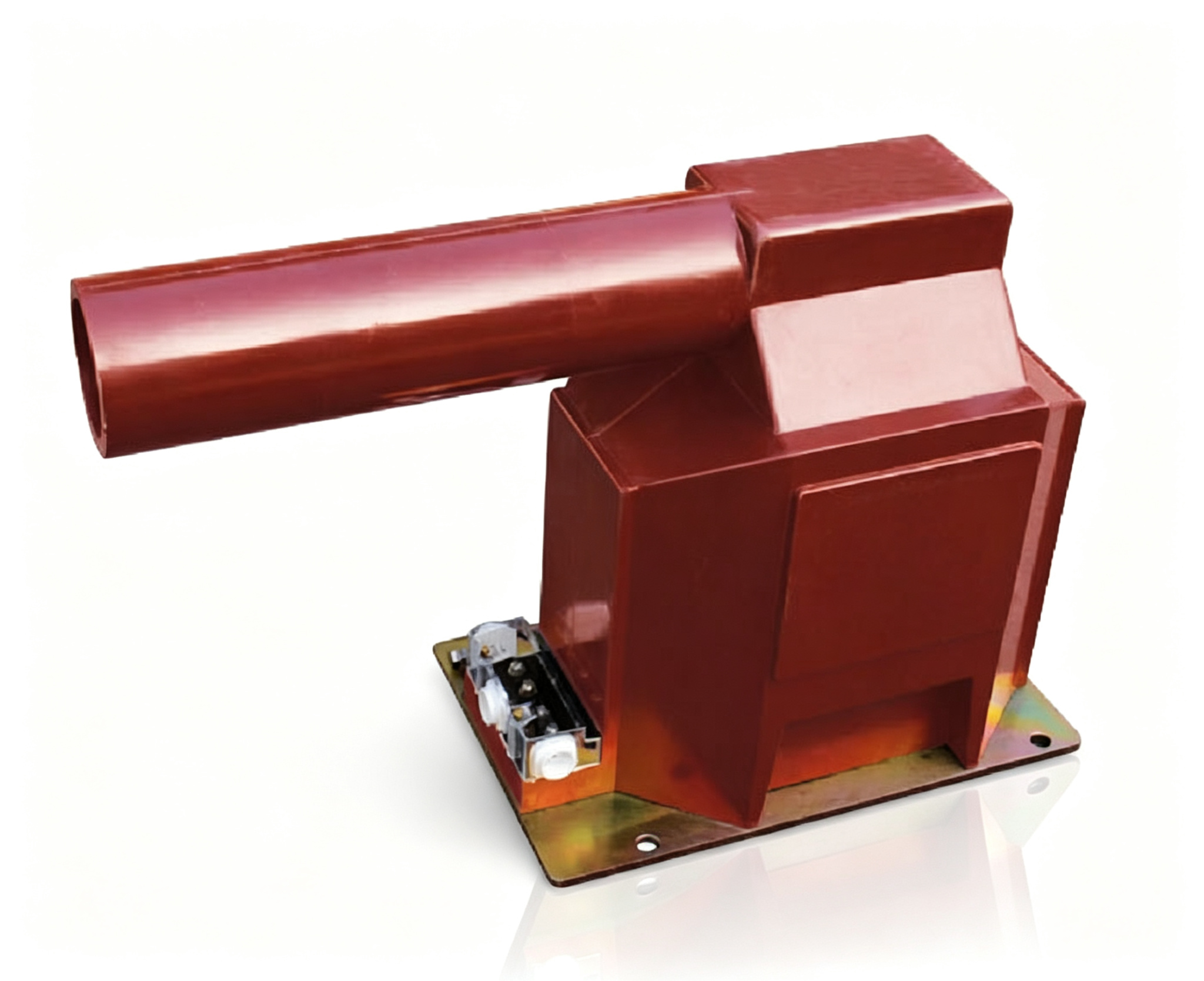
Temperature rise: the requirement that shows up years later
Temperature rise is verified at rated voltage and the burden that produces the highest losses, held until thermal equilibrium. The standard limits the rise, not an absolute temperature, because a substation ambient is not fixed — which is why two units with identical nameplate data can age very differently. For cast-resin VTs the hot spot sits inside the primary winding; for oil-immersed units it is the top-oil temperature. A design that passes ratio and PD but runs hot will drift out of class within a few years, so request the type-test report together with the routine-test report.
Test programme at a glance (IEC 61869-3)
| Test | What it proves | Routine (100%) | Type test |
|---|---|---|---|
| Power-frequency withstand | Insulation integrity of primary and secondary | Yes | — |
| Partial discharge at 1.2 Um/√3 | Absence of voids and delamination | Yes | — |
| Ratio and phase error at 80 / 100 / 120% Un | Accuracy class and burden window | Yes | — |
| Temperature rise at rated voltage and burden | Thermal design margin | — | Yes |
| Voltage factor 1.9 Un for 8 h | Survival of an earth fault on an isolated system | — | Yes |
| Lightning impulse | Insulation coordination with the system BIL | — | Yes |
By selecting KEMA-certified PTs manufactured under IEC 61869-3 guidelines, utility operators ensure reliable revenue billing and protection relay performance for decades.