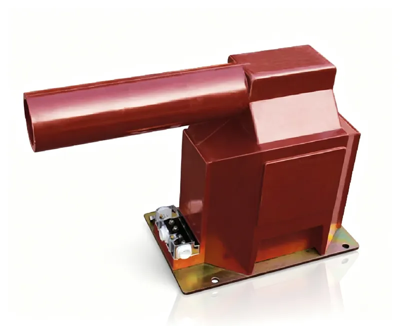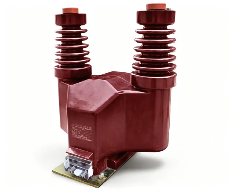
A potential transformer works like any other transformer: two windings share one magnetic core, and the voltage ratio follows the turns ratio. What makes it special is not the physics but the job — it has to reproduce the system voltage accurately enough for a meter to bill on it, while keeping the secondary at a safe 100 V or 110 V.
The basic principle
When the primary winding is connected across the system voltage, alternating current flows and sets up a magnetic flux in the core. That flux induces a voltage in the secondary winding. If the primary has 1,000 turns and the secondary has 10, the secondary voltage is one hundredth of the primary voltage. The transformer does not create energy; it trades voltage for current, and the secondary current is correspondingly small.
Two details separate a PT from a power transformer. First, the core runs at low flux density so the output stays linear and the error stays inside the accuracy class. Second, the secondary is deliberately small — a few tens of volt-amperes — because a PT feeds instruments, not loads.
The turns ratio is the whole trick
Because the ratio is fixed, every reading at the secondary can be scaled back to the primary. That is why PT secondaries are standardised: a meter does not need to know whether it is installed on a 10 kV or a 35 kV feeder, it only needs to be told the ratio.
| System voltage (line-to-line) | Secondary voltage | Ratio | Secondary reads at nominal primary |
|---|---|---|---|
| 10 kV | 100 V | 100:1 | 100 V |
| 11 kV | 110 V | 100:1 | 110 V |
| 33 kV | 110 V | 300:1 | 110 V |
| 35 kV | 100 V | 350:1 | 100 V |
Standardising the secondary means one meter or relay design works on every voltage level. Protection relays are built around a 100 V or 110 V input, and meters are calibrated for it — the ratio in the PT is what tells the panel what it is really measuring.
What is inside a potential transformer
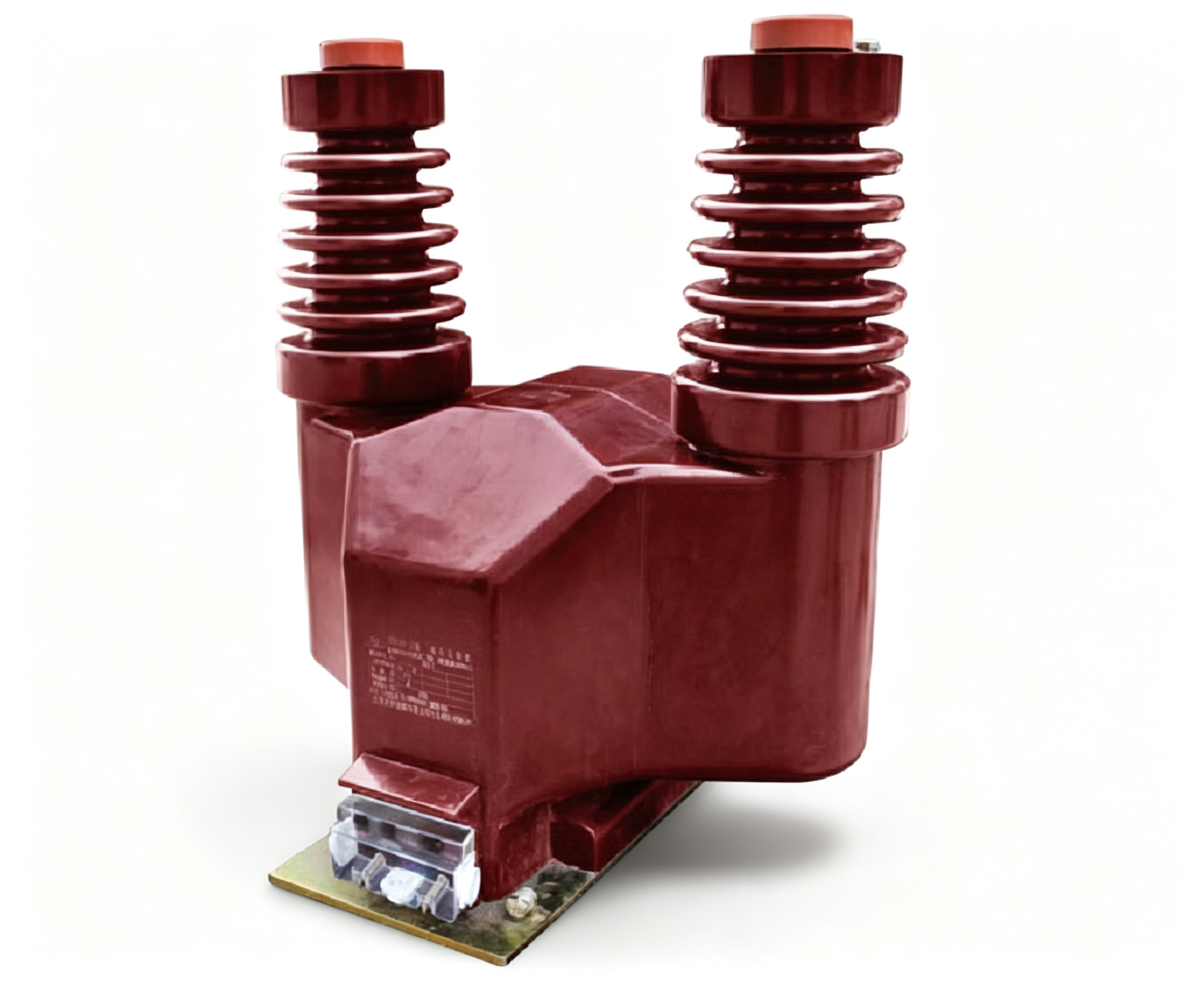
An inductive PT is a laminated steel core, a primary winding with many turns of fine wire, a secondary winding with fewer turns, and insulation between them and to earth. In a medium-voltage indoor unit the whole assembly is cast in epoxy resin, which provides the insulation and protects the windings from moisture. The terminals are brought out to a small secondary terminal box, and the primary is connected to the busbar or cable compartment.
Burden and accuracy: how a PT is rated
Accuracy is only guaranteed up to the rated burden. A PT rated 30 VA at class 0.5 will meet 0.5 near 30 VA; connect 60 VA of meters and relays and it will still work, but the errors will exceed the class. This is the same trap as oversizing a current transformer: the ratio looks right, the reading at full load looks right, and the error appears only when the load is light or the power factor shifts.
| Class | Ratio error at rated voltage | Typical use |
|---|---|---|
| 0.1 | ±0.1% | Laboratory and reference metering |
| 0.2 | ±0.2% | Revenue metering |
| 0.5 | ±0.5% | Commercial and industrial metering |
| 1.0 | ±1.0% | Indication only |
| 3P | ±3% at the voltage factor | Protection |
How a PT is connected
The primary is connected phase-to-phase or phase-to-earth, depending on whether the secondary must give line voltage or phase voltage. For a residual winding used in earth-fault detection, three secondary windings are connected in open delta so their voltages add only when an earth fault appears. The secondary side goes to the meter or relay through a fuse or miniature circuit breaker, and the secondary is earthed at one point.
This is the opposite of a current transformer. Shorting a live CT secondary is normal practice; shorting a live PT secondary produces a large current and can destroy the winding. Isolate the primary or remove the fuse before working on the secondary circuit.
| Connection | Primary | Secondary gives | Used for |
|---|---|---|---|
| Phase-to-phase | Between two phases | Line voltage (100 V) | Metering, over-voltage, sync-check |
| Phase-to-earth | Phase to earth | Phase voltage (100/√3 V) | Earth-fault and voltage supervision |
| Open delta (residual) | Three phases | ≈100 V only during an earth fault | Residual voltage relay |
Quick answers (FAQ)
| Question | Answer |
|---|---|
| Does a PT work on DC? | No. It relies on alternating flux; a DC voltage produces no steady secondary output. |
| Why does my PT secondary read 0 V? | Check the primary fuse first, then the secondary MCB, then the wiring polarity. |
| Can I connect two meters to one PT? | Yes, if the total burden stays within the rated VA. |
| What is the voltage factor for? | It defines how much overvoltage the PT can stand during an earth fault, for a stated time. |
| Does the secondary need earthing? | Yes, at one point, for safety if the primary insulation fails. |
So the working principle is simple — a fixed turns ratio and a low-flux core — but the engineering is in the details: keep the secondary burden inside the rating, earth one point of the secondary, protect it with a fuse, and never short it while the primary is live.