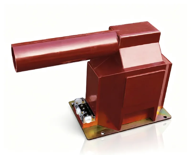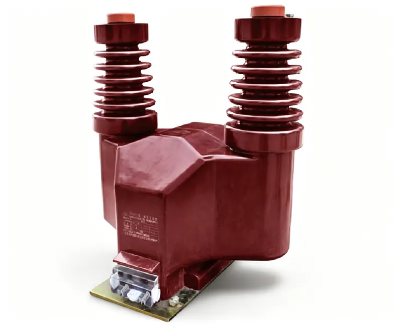
A potential transformer (PT) is a small, precision transformer that steps high voltage down to a low, safe value so meters, relays and control devices can read it. If you have ever seen a substation drawing marked "PT" or "VT" next to a 10 kV or 35 kV busbar, this is that device. It is not there to power equipment; it is there to give an accurate, isolated copy of the system voltage.
What is a potential transformer?
A potential transformer is an instrument transformer connected in parallel with the circuit it measures. Its primary winding sees the full system voltage, and its secondary winding produces a standard output — usually 100 V or 110 V line-to-line — that is proportional to the primary voltage. The ratio between the two is fixed by the turns, so a reading on the secondary can be scaled back to the real system voltage.
“Potential transformer” and “voltage transformer” (VT) describe the same instrument. IEC standards use voltage transformer; North American practice and many datasheets use potential transformer. If a project mixes the two, do not treat them as different products.
The key point is accuracy, not power. A PT delivers only a few tens of volt-amperes — enough for a meter coil or a relay input, not enough to run a motor. That is why its core and windings are designed around error limits and phase displacement rather than around heating.
Where potential transformers are used
PTs appear wherever a system voltage has to be measured or supervised: revenue metering on incoming feeders, voltage inputs to protection relays, synchronising and voltage-check schemes, automatic voltage regulation, and SCADA or power-quality monitoring. In a typical 10 kV switchgear panel, one PT feeds the meter, the relay and the panel voltmeter at the same time.
| Application | Typical accuracy class | What it feeds |
|---|---|---|
| Revenue metering | 0.2 or 0.5 | Energy meter |
| Protection | 3P | Over/under-voltage, distance, sync-check relays |
| Indication and SCADA | 1.0 | Panel voltmeter, RTU, power quality meter |
| Earth-fault detection | 3P (residual winding) | Residual voltage relay |
Main types of potential transformers
There are three families you will meet in practice. Inductive PTs are the workhorse for medium voltage: an iron core with primary and secondary windings, cast in epoxy resin for indoor use or oil-filled for outdoor and higher voltages. Capacitive voltage transformers (CVTs) divide the voltage with a capacitor stack first, which becomes economic above roughly 110 kV and can double as a power-line carrier coupler. Gas-insulated PTs are built into SF6 switchgear, where space is the deciding factor.
| Type | Typical voltage | Where it is used | Note |
|---|---|---|---|
| Inductive, cast resin | 0.66–40.5 kV | Indoor switchgear | Compact, maintenance-free |
| Inductive, oil-immersed | 35–145 kV | Outdoor substations | Better insulation at high voltage |
| Capacitive (CVT) | 110–765 kV | EHV transmission | Also used for PLC coupling |
| SF6 gas-insulated | 72.5–550 kV | GIS substations | Fits inside the gas compartment |
What to look for on a PT nameplate
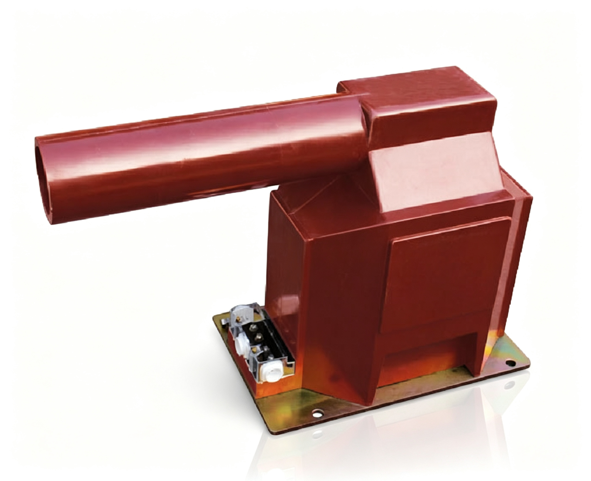
A PT nameplate is short, but four numbers decide whether the device fits your panel: rated primary voltage, rated secondary voltage, accuracy class and rated burden. A fifth item, the voltage factor, tells you how long the PT can survive an earth fault on an unearthed system.
| Nameplate item | Example | Why it matters |
|---|---|---|
| Rated primary voltage | 35 kV, 35/√3 kV | Must match the system nominal voltage and connection |
| Rated secondary voltage | 100 V, 110 V, 100/√3 V | Must match the meter and relay input |
| Accuracy class | 0.2, 0.5, 1.0, 3P | Decides whether billing or protection can rely on it |
| Rated burden | 15 VA, 30 VA | Accuracy is only guaranteed up to this load |
| Voltage factor | 1.2 / 1.9 for 8 h | Survival during an earth fault on an isolated system |
The practical rule is to start from the secondary side: add up the burden of every device you will connect, choose an accuracy class that matches the tariff or the protection scheme, and only then pick the primary voltage and ratio. Selecting a PT by voltage alone is how panels end up with a meter that reads correctly at full load and drifts at light load.
Quick answers (FAQ)
| Question | Answer |
|---|---|
| Is a PT a step-up or step-down transformer? | Always step-down: high system voltage in, standard 100 V or 110 V out. |
| Does a PT supply power to equipment? | No. It supplies a signal, typically a few tens of VA. |
| What happens if a PT secondary is shorted? | A large current flows and the PT can be damaged. Unlike a CT, a PT secondary must never be short-circuited. |
| Can one PT feed metering and protection? | Yes, if it has separate cores and the burden of both is within the rating. Many units offer a metering core plus a protection core. |
| PT or CVT for 220 kV? | CVT is normally more economical and can also carry power-line carrier signals. |
In short: a potential transformer is the instrument that turns an unsafe system voltage into a safe, accurate, proportional signal. Choose it by secondary burden and accuracy class first, and by voltage and type second — that is the order in which it will be judged in service.