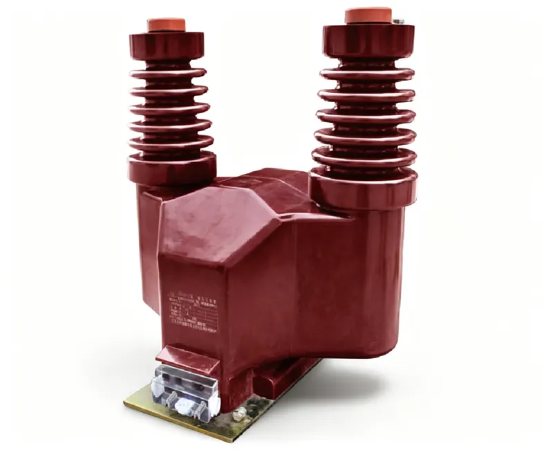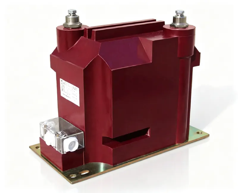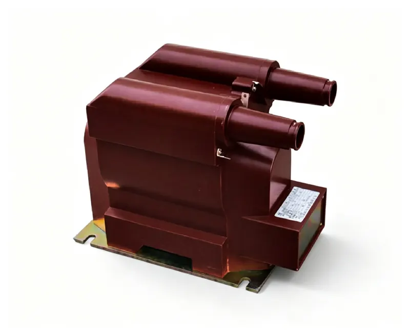
Ask three suppliers for a “10 kV, class 0.2 voltage transformer” and you will receive three different products. One is 30 VA, another 50 VA; one is rated 1.2/1.9/30 s, another 1.2/1.9/8 h; one is tested at 28 kV power frequency, another at 42 kV. All three can honestly claim to “comply with IEC 61869-3” — because the standard defines a menu of ratings, not a single product.
This guide walks through that menu in the order an engineer actually meets it: scope, the ratings on the nameplate, the voltage factor that decides whether the unit survives an earth fault, the tests that prove it, and the mistakes that show up most often in purchase specifications.
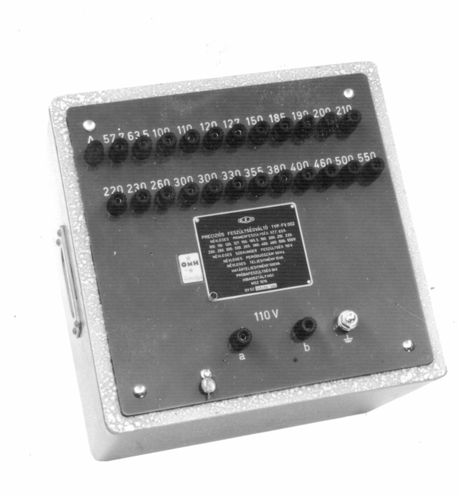
- IEC 61869-3:2011 covers new inductive voltage transformers (VT/PT) for measuring and protection, 15–100 Hz. It replaced IEC 60044-2 and is read together with IEC 61869-1.
- Measuring classes: 0.1 / 0.2 / 0.5 / 1.0 / 3.0; protective classes: 3P / 6P. Accuracy is guaranteed only from 80 % to 120 % of rated voltage.
- Standard outputs come in two families: 1.0–10 VA at pf = 1 (range I) and 10–100 VA at pf = 0.8 lagging (range II).
- Rated voltage factor is a pair — a multiplier and a duration: 1.2 continuous, 1.5/30 s, 1.9/30 s, 1.9/8 h. Quoting “1.9” without the duration is not a specification.
- Routine tests on every unit: power-frequency withstand on the primary, partial discharge, and accuracy.
1. What the standard covers — and what it deliberately leaves out
Clause 1 of IEC 61869-3 defines a narrow, practical scope: new inductive voltage transformers used with electrical measuring instruments and protective devices, at frequencies from 15 Hz to 100 Hz. Every transformer covered must be suitable for measurement; some are additionally suitable for protection, and a unit sold for both purposes must satisfy every clause.
Four exclusions matter when you read a datasheet:
- Three-phase transformers are not specified in detail. A few clauses reference them, but the requirements are written around single-phase units.
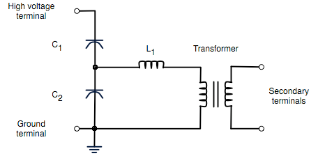
- Capacitive voltage transformers (CVT) live in IEC 61869-5, not here. A CVT datasheet citing 61869-3 is citing the wrong document.
- Electronic and low-power voltage sensors are covered by IEC 61869-6, -7 and -11.
- Frequencies outside 15–100 Hz (aircraft 400 Hz, for example) are outside the scope.
Part 3 does not stand alone. It is “additional requirements”: anything not explicitly modified is inherited from IEC 61869-1 (general requirements). This is why a VT certificate usually lists two standard numbers, and why a test report that cites only part 3 is incomplete.
2. How it relates to IEC 60044-2 and the rest of the family
IEC 61869-3:2011 replaced IEC 60044-2 (inductive voltage transformers). The replacement was not a cosmetic renumbering: the 61869 series restructured the whole instrument-transformer family and moved common requirements into part 1. New or rewritten clauses in part 3 carry numbers from 301 upward — a quick way to tell, inside a clause reference, whether you are reading something inherited from part 1 or something specific to voltage transformers.
| Part | Scope | Replaced |
|---|---|---|
| IEC 61869-1 | General requirements for all instrument transformers | — |
| IEC 61869-2 | Additional requirements for current transformers | IEC 60044-1, 60044-6 |
| IEC 61869-3 | Additional requirements for inductive voltage transformers | IEC 60044-2 |
| IEC 61869-4 | Combined transformers | IEC 60044-3 |
| IEC 61869-5 | Capacitive voltage transformers | IEC 60044-5 |
| IEC 61869-6 / -7 | Electronic instrument transformers and voltage sensors | IEC 60044-7 / -8 (partly) |
Practical consequence for procurement: an old project specification written against 60044-2 is still technically readable, but the test list and the partial-discharge requirements may differ. When a tender says “IEC 60044-2 or equivalent”, confirm in writing that 61869-3 is acceptable — otherwise you may be asked to repeat type tests.
3. The ratings that decide everything
Five ratings appear on every VT nameplate. They are interdependent: change one and the others move.
3.1 Rated primary voltage
For a transformer connected between phase and earth (the normal case for a phase-to-earth VT), the rated primary voltage is the system voltage divided by √3; for a unit connected phase-to-phase it is the system voltage itself. The standard points at IEC 60038 for the list of standard system voltages, which is why you see 10 kV, 11 kV, 20 kV, 33 kV, 35 kV and 66 kV side by side in different countries.
3.2 Rated secondary voltage
The standard does not pick one value; it records common practice:
| Practice | Standard secondary values | Notes |
|---|---|---|
| European practice | 100 V, 110 V | 200 V for extended secondary circuits |
| North American practice | 120 V (distribution), 115 V (transmission) | 230 V for extended circuits |
| Phase-to-earth units | the above divided by √3 | 100/√3 V ≈ 57.7 V is the classic value |
The division by √3 keeps the ratio unchanged: 10/√3 kV to 100/√3 V is still 100:1.
3.3 Rated output (burden)
Here the standard is unusually prescriptive, and this is where most “equivalent” quotes quietly diverge. Outputs are grouped into two burden ranges:
| Burden range | Power factor | Standard rated outputs |
|---|---|---|
| Range I | 1.0 (resistive) | 1.0 · 2.5 · 5.0 · 10 VA |
| Range II | 0.8 lagging | 10 · 25 · 50 · 100 VA |
For a three-phase transformer, the rated output is per phase — a detail that has caused more than one 3× undersized installation.
The second number on the nameplate is the rated thermal limiting output: the apparent power the winding can deliver at rated voltage without exceeding its temperature-rise limits. Standard values are 25, 50 and 100 VA and their decimal multiples, at unity power factor. Accuracy is not guaranteed at that output — the thermal limit only says the unit will not overheat. Keep the two apart: 100 VA accuracy and 200 VA thermal limit is a perfectly normal pairing.
Residual-voltage windings (broken delta) have their own thermal rating, referred to 8 hours rather than continuous operation, because they are loaded only during earth faults.
3.4 Accuracy class for measurement
Five standard classes: 0.1, 0.2, 0.5, 1.0, 3.0. The class number is the maximum permissible voltage (ratio) error in percent, at rated voltage and rated burden. Phase displacement has its own limit:
| Class | Voltage error (± %) | Phase displacement (± min) | Phase displacement (± crad) |
|---|---|---|---|
| 0.1 | 0.1 | 5 | 0.15 |
| 0.2 | 0.2 | 10 | 0.3 |
| 0.5 | 0.5 | 20 | 0.6 |
| 1.0 | 1.0 | 40 | 1.2 |
| 3.0 | 3.0 | not specified | |
Two conditions travel with that table and are frequently dropped from datasheets:
- Voltage window: the limits hold at any voltage between 80 % and 120 % of rated voltage — not at 100 % only.
- Burden window: for range I, any burden from 0 VA to 100 % of rated; for range II, 25 % to 100 % of rated at 0.8 lagging. Below 25 % the transformer is allowed to drift outside the class.
When a VT has two separate secondary windings, they interfere with each other magnetically. The standard therefore requires an output range to be declared for each winding (25–100 % by default), with the other winding loaded anywhere from zero to its rated value during the test. A two-winding VT specified without output ranges is under-specified.
3.5 Protective classes 3P and 6P
Protection windings are designated by the same percentage convention, followed by P:
| Class | Voltage error (± %) | Phase displacement (± min) | Phase displacement (± crad) |
|---|---|---|---|
| 3P | 3.0 | 120 | 3.5 |
| 6P | 6.0 | 240 | 7.0 |
The evaluation window is different from measurement, and this is the part engineers miss: the limits apply at 5 % of rated voltage and at rated voltage multiplied by the rated voltage factor (1.2, 1.5 or 1.9). At 2 % of rated voltage the permitted errors are twice as large. In other words, a 3P winding is specified for the whole range a relay actually sees, from a few percent during a close-in fault up to the voltage factor during an earth fault.
Residual-voltage windings must be class 6P or better; if the winding is used purely for damping ferroresonance, an accuracy class is not required at all.
4. Rated voltage factor: the parameter that decides survival
During a single-phase earth fault, the voltage across a phase-to-earth VT rises. How far, and for how long, depends on how the network is earthed — and the transformer must ride through it without saturating, overheating or losing accuracy. IEC 61869-3 expresses this as a pair of values:
| Rated voltage factor | Rated duration | Typical use |
|---|---|---|
| 1.2 | continuous | all units |
| 1.5 | 30 s | standard option |
| 1.9 | 30 s | effectively earthed systems, fault cleared quickly |
| 1.9 | 8 h | isolated or resonant-earthed systems, fault may persist for hours |
Two rules of thumb follow, and they explain most of the confusion in tender documents:
- In an effectively earthed network, an earth fault is cleared in well under a second, so 1.9 for 30 s is the normal choice.
- In an isolated or resonant-earthed network, a single-phase earth fault can run for hours while the network keeps supplying customers; the healthy-phase voltage stays at √3 times normal. That is why the same 1.9 multiplier appears with an 8-hour duration.
A VT rated 1.9/30 s installed in an 8-hour regime will not fail on the first fault. It will saturate, overheat, and lose its accuracy — or its insulation — on a fault that lasts longer than half a minute. The multiplier alone tells you nothing; the duration is the specification.
5. Insulation level and partial discharge
The rated insulation level is not set by part 3 alone: it follows the highest voltage for equipment (Um) in IEC 61869-1, which in turn follows IEC 60071-1. Common values for medium-voltage units:
| Um (kV) | Power-frequency withstand (kV) | Lightning impulse withstand (kV) |
|---|---|---|
| 3.6 | 10 | 40 |
| 7.2 | 20 | 60 |
| 12 | 28 | 75 |
| 24 | 50 | 125 |
| 36 | 70 | 170 |
Chinese practice under GB/T 20840.3 often specifies higher power-frequency values on the same impulse level — 42 kV for Um 12 kV, 95 kV for Um 40.5 kV. That is national practice, not an IEC requirement, and it is one of the first things to check when comparing a Chinese datasheet with a European one.
One small clause is worth remembering because it appears in every factory test: the earthed terminal of the primary winding must withstand 3 kV power frequency (clause 5.3.3.301). It protects the reduced-insulation end of a phase-to-earth unit.
Partial discharge is a routine test, not a type test. The standard's limit is expressed in picocoulombs; many utilities tighten it to 10 pC or 5 pC in their own specifications. Two practical notes: ask for the measured value rather than a “pass” stamp, and make sure the test is done at the same voltage the specification quotes — a PD figure without its test voltage is unreadable.
6. The test list
| Category | Tests | What it proves |
|---|---|---|
| Type tests (once per design) | Temperature rise · lightning impulse on primary · EMC · accuracy · short-circuit withstand | The design can survive the environment and the fault current |
| Routine tests (every unit) | Power-frequency withstand on primary · partial discharge · accuracy | This particular unit is free of defects and meets its class |
| Special tests (on request) | Capacitance and dielectric dissipation factor · internal arc fault | Dielectric health over time; safety under internal failure |
If a supplier cannot produce a type-test report for the exact design being offered — not a “similar” design, not a sister model — the accuracy claim is a calculation, not a measurement.
7. Reading a real nameplate
Take a typical 10 kV indoor cast-resin unit from our catalogue, the JDZ10-10-6R:
10 kV / 0.1 kV · 0.2, 0.5, 1.0 · 30 / 50 / 100 VA · 12/42/75 kV · 50/60 Hz
Decoded:
- 10 kV / 0.1 kV — ratio 100:1. If it is connected phase-to-earth on a 10 kV system, the primary rating should strictly be 10/√3 kV; a 10 kV unit is a phase-to-phase rating.
- 0.2, 0.5, 1.0 — three classes at three burdens, normally read straight across: 0.2 at 30 VA, 0.5 at 50 VA, 1.0 at 100 VA. Buying “class 0.2” and then loading it to 100 VA is a common and expensive mistake.
- 30 / 50 / 100 VA — the burden range in which those classes hold. Which power factor applies (0.8 lagging or unity) is not on this line; it must be in the specification.
- 12/42/75 kV — Um / power-frequency withstand / lightning impulse, in the Chinese convention.
What the nameplate does not tell you: the rated voltage factor and its duration, and whether the accuracy applies at 0.8 or 1.0 power factor. Those two omissions are exactly where a purchase specification should be explicit.
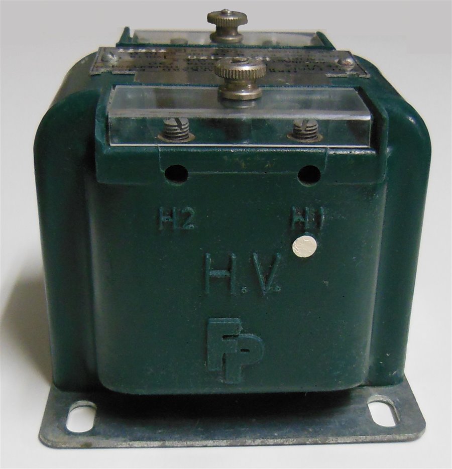
The other half of clause 6.13 is not text but hardware — the terminal markings. A phase-to-earth unit marks its primary ends H1/H2 (or A/N), its secondary a/b, and the polarity with a dot or an embossed mark. Polarity is not cosmetic: reverse it and the phase displacement turns by 180°, while the transformer still reports a tiny ratio error. The meter or relay then works in the wrong quadrant, and no accuracy class will save you.
8. Six mistakes that keep appearing in specifications
- “Class 0.2S”. S classes belong to current transformers (IEC 61869-2). Voltage transformers have 0.1 / 0.2 / 0.5 / 1.0 / 3.0 and 3P / 6P — no S.
- Quoting burden without power factor or range. “50 VA” means nothing until you say 0.8 lagging (range II) or unity (range I), and whether the class holds from 25 % or from 0 VA.
- Quoting the voltage factor without the duration. 1.9/30 s and 1.9/8 h are different products with different core areas and prices.
- Assuming accuracy at any voltage. Outside 80–120 % of rated voltage, the class does not apply — and at 2 % of rated voltage a 3P winding is allowed twice the error.
- Mixing IEC and GB insulation values in one comparison table. 12/42/75 kV and 12/28/75 kV are both “12 kV”, but they are not the same test.
- Accepting “IEC 61869-3 compliant” as a specification. It is a family of options. The correct sentence names the class, the burden with power factor, the voltage factor with duration, the insulation level and the tests to be witnessed.
9. Frequently asked questions
Is IEC 61869-3 the same as GB/T 20840.3?
GB/T 20840.3 is the Chinese national standard for the same product family and is aligned with IEC 61869-3, but it is not a verbatim copy. Insulation coordination values, some test details and editorial structure differ; the differences have been analysed in the Chinese technical press (see references). For a project inside China, specify GB/T 20840.3 and note the IEC equivalence; for export, specify IEC 61869-3 and confirm which national deviations, if any, the buyer requires.
Does a voltage transformer have an “S” class, like 0.2S?
No. “S” (special) classes exist for current transformers, where they extend accuracy down to 1 % or 5 % of rated current for revenue metering. Voltage transformers are not specified that way; their accuracy window is 80–120 % of rated voltage. A VT datasheet offering “0.2S” is either a translation error or a copy-paste from a CT datasheet — ask for the type-test report.
What is the difference between rated output and thermal limiting output?
Rated output is the burden at which the accuracy class is guaranteed. Thermal limiting output is the burden the winding can carry at rated voltage without exceeding its temperature-rise limits — accuracy is explicitly not guaranteed there. Standard thermal values are 25, 50 and 100 VA and their decimal multiples at unity power factor.
Why is accuracy only guaranteed between 80 % and 120 % of rated voltage?
Because that is the window the standard defines for measurement. Below 80 % the core excitation is low and ratio error drifts; above 120 % saturation approaches. If your application needs accuracy outside that band — generator voltage regulators, for instance — it must be agreed separately and demonstrated by test, not assumed from the class.
Can I use a 1.2/1.9/30 s transformer in an isolated 10 kV system?
Only if earth faults are cleared within about 30 seconds. In an isolated or resonant-earthed system a single-phase fault can persist for hours, and the healthy-phase VT sees √3 times normal voltage for that whole time. Specify 1.9/8 h. The price difference is real, but smaller than replacing a failed unit and the outage around it.
Does IEC 61869-3 cover capacitive voltage transformers?
No — CVTs are covered by IEC 61869-5. Part 3 is for inductive (electromagnetic) voltage transformers only. The two families have different accuracy behaviour under transients and different test regimes; a datasheet that mixes them is a red flag.
Which tests are routine, and which can I witness?
Routine tests — performed on every unit — are power-frequency withstand on the primary, partial discharge and accuracy. Type tests (temperature rise, impulse, EMC, accuracy, short-circuit withstand) are done once per design. Both can be witnessed; for a repeat order, witnessing routine tests plus a review of the original type-test report is normally sufficient.
What is the 3 kV requirement on the earthed terminal?
Clause 5.3.3.301 requires the earthed end of the primary winding — the terminal with reduced insulation in a phase-to-earth unit — to withstand 3 kV power frequency. It is a small clause with a large safety role: it keeps the low-voltage end of the winding from flashing over to earth under impulse conditions.
How should a VT be specified in one line?
Something like: “VT, 10/√3 kV / 100/√3 V, class 0.2 at 30 VA, 0.8 lagging, rated voltage factor 1.2/1.9/8 h, insulation 12/42/75 kV, IEC 61869-3, 50 Hz, routine test report with measured PD.” Every element in that sentence closes a hole that “10 kV 0.2 class” leaves open.
10. References
- IEC 61869-3:2011, Instrument transformers — Part 3: Additional requirements for inductive voltage transformers, IEC, Geneva. IEC Webstore
- IEC 61869-1:2007, Instrument transformers — Part 1: General requirements.
- IEC 60038, IEC standard voltages.
- IEC 60044-2 (superseded), Instrument transformers — Part 2: Inductive voltage transformers.
- GB/T 20840.3, 互感器 第3部分:电压互感器的补充技术要求(Chinese national standard, aligned with IEC 61869-3).
- 傅永和, 黄超, 林展洪. 浅析 GB/T 20840.3 与 IEC 61869-3 的技术差异. 《电工电气》2020 年第 9 期. CNKI 摘要
Looking for a unit that meets a specific combination of class, burden and voltage factor? Our voltage transformer range lists the exact ratings per model — and if the combination you need is not there, it is usually a winding change rather than a new design.