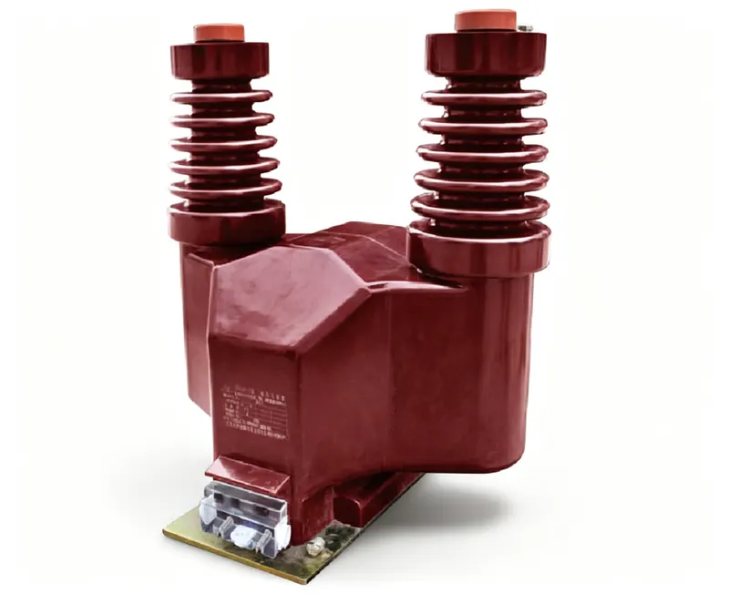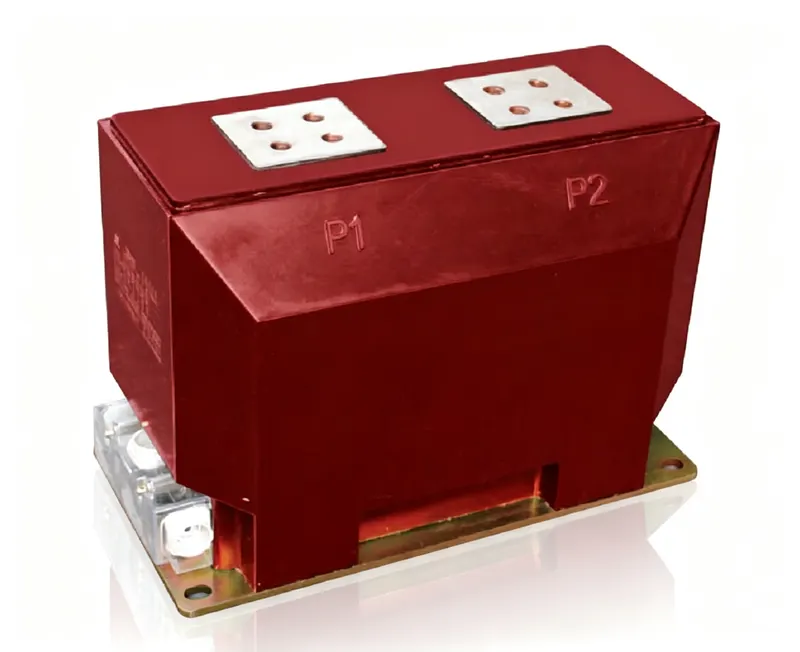
Both are instrument transformers, both step a high-level quantity down to something a meter can read, and both sit in the same switchgear panel. But a potential transformer and a current transformer do opposite jobs, and — more importantly for anyone working on the panel — their safety rules are exact opposites.
The short answer
A potential transformer measures voltage. It is connected in parallel with the circuit, its primary sees the full system voltage, and its secondary gives a standard 100 V or 110 V. A current transformer measures current. It is connected in series with the conductor, its primary is the conductor itself, and its secondary gives a standard 1 A or 5 A.
| Potential transformer (PT / VT) | Current transformer (CT) | |
|---|---|---|
| Measures | Voltage | Current |
| Connection | Parallel, across the circuit | Series, in line with the conductor |
| Primary | Many turns of fine wire | Few turns, often a bar or busbar |
| Secondary output | 100 V or 110 V | 1 A or 5 A |
| Typical burden | 10–50 VA | 5–30 VA |
| Safe secondary state | Open circuit (never short it) | Short circuit (never open it) |
| Accuracy classes | 0.1 / 0.2 / 0.5 / 1.0 / 3P | 0.2S / 0.5S / 5P20 / 5P30 |
Why the hazards are opposite
A CT is a current source: its secondary current is forced by the primary current, so opening the secondary drives the core into saturation and produces a dangerous voltage spike. A PT is a voltage source: its secondary voltage is forced by the primary voltage, so shorting the secondary draws a large current and can burn the winding.
CT: short before you open. PT: never short a live secondary. Most panel work goes wrong when someone applies the habit from the other device.
That is also why the test practices differ. CT testing uses shorting links and test blocks with a “short first, open second” sequence; PT testing uses fuses, MCBs and voltage injection, with the primary isolated before the secondary is disturbed.
How to tell them apart on a drawing
The fastest giveaway is the ratio notation. A PT ratio is written in volts — 10/0.1 kV, 35/0.1 kV, 110/0.11 kV. A CT ratio is written in amperes — 600/5 A, 400/1 A. If the numbers carry a V, it is a PT; if they carry an A, it is a CT.
| On the drawing | Potential transformer | Current transformer |
|---|---|---|
| Ratio notation | 10/0.1 kV, 600/√3 V | 600/5 A, 400/1 A |
| Symbol | Two circles with a V marker | Two circles with an A marker (or a bar through the symbol) |
| Mounted | On the busbar or in a separate compartment | Around the busbar or cable, or in a through-window housing |
| Secondary terminals | Marked a, b, c, n | Marked S1, S2 (per core) |
Can one replace the other?
No. A PT cannot measure current — its primary is a high-resistance winding connected across the voltage, not a conductor carrying the load current. A CT cannot measure voltage — it is designed to work with the primary current, and with no current there is no secondary signal. Panels that need both quantities use both devices, often on the same feeder.
One practical case does cause confusion: a single-phase PT can be used to derive an approximate voltage signal for a protection relay, and a CT can feed a current input of the same relay. They look alike in the drawing because both are two-terminal instrument transformers, but the relay input they land on is different — a voltage input versus a current input.
Quick answers (FAQ)
| Question | Answer |
|---|---|
| Is a PT just a small power transformer? | No. It is designed for accuracy and low output, not for transferring power. |
| Which is bigger, a PT or a CT? | For the same voltage level a PT is usually larger, because it must withstand the full system voltage across its primary. |
| Do both need a fuse? | A PT is normally protected by a primary fuse or MCB; a CT is never fused on the secondary. |
| Can a CT give a voltage signal? | Only through a burden resistor, and that is a measurement trick, not a normal application. |
| Why 100 V and 5 A? | Both are legacy standards that let one meter design work across all voltage and current levels. |
The simplest way to remember it: a PT is connected across the line and tells you how many volts; a CT is connected in the line and tells you how many amps. Get the connection right, and never carry the safety habit from one over to the other.