



Selecting a 10kV indoor current transformer for KYN28 switchgear is not simply a matter of matching the busbar current. The CT must simultaneously satisfy metering accuracy, protection performance, thermal and dynamic withstand, and the physical constraints of the withdrawable truck compartment. A mismatch in any one of these parameters leads to measurement errors, protection misoperation, or mechanical interference during racking. This guide explains how to approach ratio, burden and accuracy class selection for cast-resin CTs used in KYN28 metal-clad switchgear.
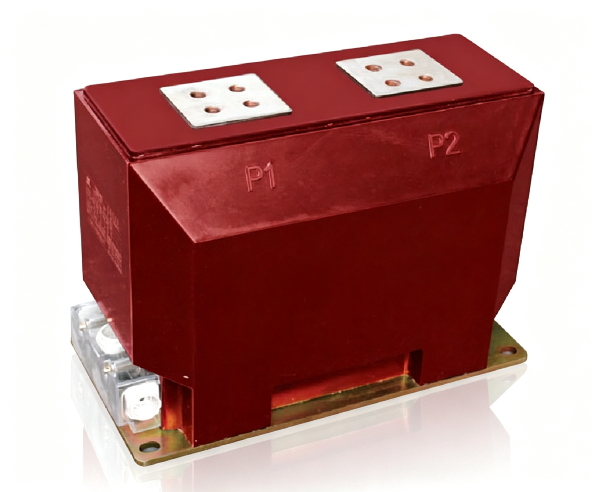
Application context: KYN28 switchgear is a metal-clad, withdrawable design commonly used in 10kV distribution systems. The CT is typically mounted on the busbar or cable compartment and must fit within the phase spacing and insulation requirements of the cabinet. Indoor epoxy cast CTs such as the LZZBJ9-10GWA,B,C are designed for this environment, with models offering accuracy classes 0.2S, 0.5, 5P20 and 5P30. Busbar-type designs like the LMZ9-10 are also used where the primary conductor passes through the window opening.
Ratio selection: The primary ratio should be chosen so that the expected normal load current falls between 40% and 60% of the CT primary rating. This keeps the core in a favourable region for accuracy while leaving headroom for overload. For example, if the maximum continuous load is 400 A, a 600/5 A or 800/5 A ratio may be appropriate depending on future expansion. The secondary rating is usually 5 A or 1 A; 5 A is common in KYN28 installations, while 1 A reduces burden on long secondary runs. Always confirm the ratio against the relay and meter settings.
| Max continuous load | Suggested ratio | Normal-load position | Comment |
|---|---|---|---|
| 150 A | 300/5 A | 50% | Comfortable headroom for overload |
| 250 A | 400/5 A | 62% | Use 600/5 A if load varies widely |
| 400 A | 800/5 A | 50% | Leaves room for future expansion |
| 600 A | 1000/5 A | 60% | Check thermal rating of the panel |
Burden calculation: The CT burden is the total impedance of the secondary circuit, including relay coils, meter coils, wiring resistance and contact resistance. The rated burden of the CT must be greater than or equal to this total. For metering cores, the burden is usually small, but for protection cores the relay and wiring can add significant load. Calculate the loop resistance using the cable length, cross-section and resistivity, then add the device burden from the manufacturer's data. A CT with a rated burden of 15 VA or 20 VA is common for protection cores in distribution switchgear, but the exact value must be verified against the connected devices.
| Item | Basis | Burden at 5 A |
|---|---|---|
| Secondary cable loop | 60 m of 4 mm² copper, R ≈ 0.26 Ω | ≈ 6.6 VA |
| Relay current input | Manufacturer data | 0.5 VA |
| Meter | Manufacturer data | 1.0 VA |
| Links and contacts | Allowance | 0.5 VA |
| Total | ≈ 8.6 VA → 15 VA rating is adequate |
Accuracy class for metering: Metering cores are specified by accuracy class and rated burden. Class 0.5 is typical for commercial and industrial billing, while class 0.2 or 0.2S is used where higher accuracy is required, especially at low currents. The 'S' suffix indicates extended current range accuracy, meaning the CT maintains its accuracy class from 1% to 120% of rated current. For KYN28 feeders with variable load, a 0.2S core can be beneficial. The LZZBJ9-10GWA,B,C offers 0.2S and 0.5 classes, making it suitable for both metering and protection duties in one unit.
Accuracy class for protection: Protection cores are defined by composite error at the accuracy limit primary current. Classes such as 5P20 and 5P30 mean a composite error of 5% at 20 or 30 times the rated primary current. The higher the ALF (accuracy limit factor), the better the CT can reproduce fault current without saturation. For KYN28 feeders protected by overcurrent relays, 5P20 is often sufficient, but where high fault levels or differential protection are involved, 5P30 may be needed. The LZZBJ9-10GWA,B,C provides both 5P20 and 5P30 options, allowing the engineer to match the protection core to the fault level and relay setting.
Dual-core configuration: Most KYN28 CTs use separate cores for metering and protection. This allows the metering core to be optimised for accuracy at normal load and the protection core for performance at fault current. The two cores are magnetically independent, so a saturation in the protection core does not affect the metering core. When ordering, specify the ratio, class and burden for each core separately. For example, a CT might have a 600/5 A metering core class 0.5, 15 VA and a 600/5 A protection core class 5P20, 20 VA.
| Core | Ratio | Class | Rated burden | Duty |
|---|---|---|---|---|
| 1 — metering | 600/5 A | 0.2S | 15 VA | Billing, wide load range |
| 2 — protection | 600/5 A | 5P20 | 20 VA | Overcurrent relay |
| 3 — earth fault | 600/5 A | 5P20 | 15 VA | Residual / core-balance scheme |
Thermal and dynamic withstand: The CT must withstand the short-circuit current of the system for the duration specified by the switchgear rating. The rated short-time thermal current (Ith) and dynamic current (Idyn) are usually given for 1 s or 3 s. These values must exceed the prospective fault current at the installation point. For 10kV distribution systems, typical values are 20 kA/1s or 25 kA/1s, but the actual value must be taken from the system study. The CT's primary conductor and casting must be rated accordingly. The LZZBJ9-10GWA,B,C is designed for 12 kV applications and is available with short-time ratings suitable for KYN28 switchgear.
Physical and installation considerations: KYN28 switchgear has limited space in the CT compartment. Check the CT dimensions, mounting hole pattern and primary terminal orientation against the cabinet drawing. Busbar-type CTs like the LMZ9-10 are mounted around the busbar, while block-type CTs like the LZZBJ9-10GWA,B,C are bolted to the compartment floor or busbar supports. Ensure that the CT does not interfere with the withdrawable truck movement or the earthing switch. Also verify the creepage distance and insulation level for the 10kV system, typically 12 kV rated voltage for indoor epoxy cast CTs.
Secondary wiring and earthing: The secondary terminals should be easily accessible for wiring and testing. Use shorting links on unused cores and earth the secondary circuit at one point, usually at the CT terminal or in the relay panel. The wiring cross-section must be adequate to keep the burden within the CT rating. For long runs, a 4 mm² or 6 mm² cable may be needed. Always follow the switchgear manufacturer's wiring diagram and the relevant IEC 61869 or GB/T 20840 requirements for secondary connections.
Never open-circuit a CT secondary while primary current is flowing. Short the secondary terminals before removing wiring, test links or the meter — an open secondary can develop dangerous voltage and destroy the core.
Standards and testing: Current transformers for KYN28 switchgear should comply with IEC 61869-2 or GB/T 20840.2, which cover general requirements, accuracy, burden and dielectric tests. The manufacturer's routine tests include power-frequency withstand, partial discharge and accuracy verification. Type tests may include short-time current and temperature rise. When selecting a CT, request the routine test report and confirm that the accuracy class and burden have been verified at the specified rated current. The LZZBJ9-10GWA,B,C is designed to meet these standards, but the final verification rests on the test certificates provided with the delivered units.
Full technical specifications (LZZBJ9-10GWA,B,C)
| Parameter | Value |
|---|---|
| Rated voltage | 12 kV |
| Secondary current | 5 A or 1 A |
| Accuracy class | 0.2S, 0.5, 5P20, 5P30 |
| Rated burden | 10 VA / 15 VA / 20 VA |
| Insulation level | 12/42/75 kV |
| Frequency | 50/60 Hz |
| Standard | IEC 61869 / GB/T 20840 |
Conclusion: For a 10kV indoor CT in KYN28 switchgear, start with the system fault level and load profile, then select a ratio that keeps normal current at 40–60% of rated primary. Specify separate metering and protection cores with burdens calculated from the actual secondary loop. Choose 0.5 or 0.2S for metering and 5P20 or 5P30 for protection, and verify thermal and dynamic ratings against the switchgear fault level. Confirm dimensions and mounting against the cabinet drawing before ordering. If the fault level is high or the load varies widely, a dual-core CT such as the LZZBJ9-10GWA,B,C with 0.2S and 5P30 cores is a practical choice.