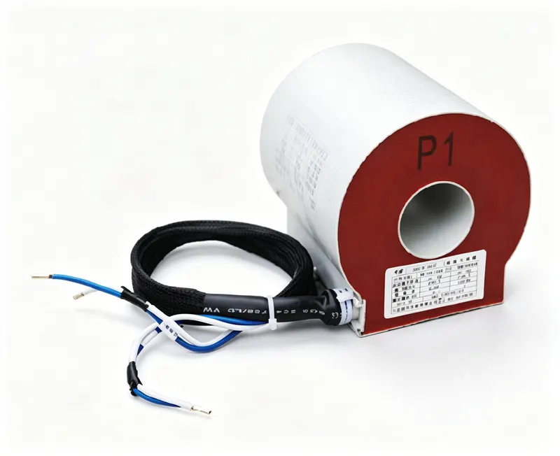
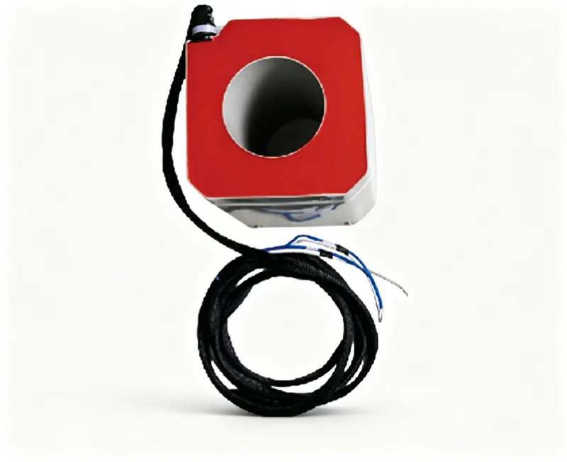
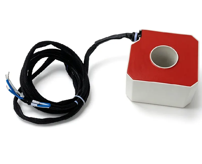
CGIS1555 Current Transformer Applied to CGIS Gas Insulated Switchgear is designed for metering and protection in power systems. Key ratings: primary voltage 20kV, accuracy class 0.2/6P(3P),0.5/6P(3P),1.0/6P(3P), rated burden 30VA / 60VA / 100VA / 100VA. Design: insulation level 24/65/125kV,18/55/105kV, Dry Epoxy Resin, 50Hz or 60Hz operation.
Indoor epoxy resin casting current transformer for CGIS gas insulated switchgear, rated 20kV, available in multiple accuracy classes and burdens.
| Parameter | Specification | Verification |
|---|---|---|
| Product Type | Current Transformer | [On Request] |
| Model Code | CGIS1555 | Factory nameplate marking |
| Primary Voltage | 20kV | Rated voltage test (IEC 61869-1/3) |
| Secondary Current | [On Request] | Ratio check at rated frequency |
| Accuracy Class | 0.2/6P(3P),0.5/6P(3P),1.0/6P(3P) | Accuracy test (IEC 61869-2 / IEEE C57.13) |
| Rated Burden | 30VA / 60VA / 100VA / 100VA | Burden test at rated VA |
| Insulation Type | Dry Epoxy Resin | Dielectric tests per standard |
| Insulation Level (BIL) | 24/65/125kV,18/55/105kV | Power-frequency & lightning impulse withstand |
| Standards | [On Request] | Certified to listed standards |
| Frequency | 50Hz or 60Hz | Per IEC 61869-1 |
| Environment | [On Request] | Per datasheet limits |
Ideal For
Not Recommended For
For current transformers, secondary terminals are 1S1/1S2 for the main winding and 2S1/2S2 for the protection winding. Never open-circuit the secondary of a CT while energized - hazardous voltage. Ground the secondary winding at one point.
Compliant with: [On Request]
S_total = ΣS_instrument + I₂² × (ρ × 2L / A)
Q: What is the insulation level of this CT?
A: The insulation level is 24/65/125kV, meaning 24kV system, power-frequency withstand 65kV, lightning impulse withstand 125kV peak. Also available as 18/55/105kV.
Q: What are the available accuracy classes?
A: Accuracy classes are 0.2/6P(3P), 0.5/6P(3P), and 1.0/6P(3P), suitable for metering and protection.
Q: What is the rated burden?
A: Rated burden options are 30VA, 60VA, and 100VA (two windings at 100VA).
Missing fields are marked [On Request] — never fabricated. M2/M5/M6 verification rows follow IEC 61869 / IEEE C57.13 conventions.
| Accuracy class | Rated output (VA) | 40 | 50 | 60 | 75 | 100 | 125 | 150 | 200 | 250 | 300 | 400 | 500 | 600 | 750 | 1000 | 1200 |
|---|---|---|---|---|---|---|---|---|---|---|---|---|---|---|---|---|---|
| 0.2FS10 | 2.5 | — | — | — | — | 85 | 60 | 50 | 35 | 30 | 30 | 30 | 30 | 30 | 35 | 35 | 35 |
| 5 | — | — | — | — | 130 | 90 | 70 | 50 | 40 | 35 | 30 | 30 | 30 | 35 | 35 | 35 | |
| 10 | — | — | — | — | 150 | 115 | 75 | 55 | 45 | 35 | 35 | 30 | 30 | 35 | 35 | 35 | |
| 15 | — | — | — | — | — | 160 | 100 | 70 | 55 | 45 | 40 | 35 | 35 | 35 | 35 | 35 | |
| 20 | — | — | — | — | — | — | 125 | 85 | 65 | 55 | 45 | 40 | 40 | 35 | 35 | 35 | |
| 25 | — | — | — | — | — | — | — | 150 | 105 | 75 | 60 | 50 | 45 | 45 | 40 | 35 | |
| 30 | — | — | — | — | — | — | — | — | 120 | 85 | 70 | 55 | 50 | 45 | 40 | 40 | |
| 0.5FS10 | 2.5 | — | 115 | 80 | 50 | 40 | 35 | 30 | 30 | 30 | 25 | 25 | 25 | 25 | 25 | 25 | 25 |
| 5 | — | — | 130 | 75 | 60 | 45 | 35 | 30 | 30 | 30 | 25 | 25 | 25 | 25 | 25 | 25 | |
| 10 | — | — | — | 120 | 90 | 70 | 50 | 40 | 35 | 30 | 25 | 25 | 25 | 25 | 25 | 25 | |
| 15 | — | — | — | — | 120 | 90 | 65 | 55 | 40 | 35 | 30 | 25 | 25 | 25 | 25 | 25 | |
| 20 | — | — | — | — | 155 | 115 | 80 | 65 | 55 | 50 | 40 | 35 | 30 | 25 | 25 | 25 | |
| 25 | — | — | — | — | — | 140 | 90 | 75 | 65 | 55 | 45 | 35 | 30 | 25 | 25 | 25 | |
| 30 | — | — | — | — | — | — | 105 | 85 | 70 | 65 | 50 | 40 | 35 | 30 | 25 | 25 | |
| 5P10 | 2.5 | 135 | 100 | 85 | 75 | 55 | 40 | 35 | 30 | 30 | 30 | 30 | 30 | 30 | 30 | 25 | 25 |
| 10P10 | 5 | — | 135 | 120 | 85 | 70 | 55 | 50 | 45 | 40 | 35 | 30 | 35 | 30 | 30 | 30 | 30 |
| 10 | — | — | — | 145 | 110 | 95 | 80 | 70 | 60 | 50 | 45 | 45 | 35 | 35 | 35 | — | |
| 15 | — | — | — | — | 155 | 130 | 110 | 90 | 80 | 80 | 65 | 60 | 50 | 45 | 45 | 45 | |
| 20 | — | — | — | — | — | 140 | 115 | 100 | 95 | 80 | 70 | 60 | 55 | 45 | 45 | 45 | |
| 25 | — | — | — | — | — | — | 140 | 120 | 115 | 95 | 80 | 70 | 60 | 55 | 55 | 55 | |
| 30 | — | — | — | — | — | — | — | — | 140 | 130 | 110 | 95 | 80 | 65 | 60 | 60 | |
| 5P20 | 2.5 | — | 145 | 125 | 90 | 75 | 65 | 60 | 50 | 50 | 50 | 45 | 40 | 40 | 35 | 35 | 35 |
| 10P20 | 5 | — | — | 145 | 115 | 95 | 90 | 75 | 70 | 65 | 55 | 50 | 50 | 50 | 45 | 40 | — |
| 10 | — | — | — | — | 160 | 125 | 110 | 105 | 85 | 75 | 70 | 65 | 60 | 55 | 50 | — | |
| 15 | — | — | — | — | — | — | 150 | 140 | 115 | 100 | 85 | 75 | 70 | 65 | 65 | 60 | |
| 20 | — | — | — | — | — | — | — | — | 145 | 125 | 115 | 90 | 80 | 80 | 80 | 75 | |
| 25 | — | — | — | — | — | — | — | — | — | — | 150 | 135 | 105 | 95 | 95 | 90 | |
| 30 | — | — | — | — | — | — | — | — | — | — | — | 155 | 120 | 105 | 100 | 95 | |
| 5P30 | 2.5 | — | — | — | — | 130 | 105 | 90 | 85 | 75 | 70 | 65 | 55 | 55 | 55 | 50 | 50 |
| 10P30 | 5 | — | — | — | — | — | 145 | 135 | 115 | 100 | 95 | 80 | 75 | 75 | 65 | 60 | 60 |
| 10 | — | — | — | — | — | — | — | 170 | 155 | 125 | 115 | 110 | 90 | 80 | 80 | 80 | |
| 15 | — | — | — | — | — | — | — | — | — | — | 115 | 140 | 115 | 100 | 100 | 95 | |
| 20 | — | — | — | — | — | — | — | — | — | — | — | — | 140 | 125 | 120 | 110 | |
| 25 | — | — | — | — | — | — | — | — | — | — | — | — | — | — | 145 | 130 |
Dimension & outline drawing of CGIS1555 — click image to zoom / view original.
This current transformer is built for installation inside CGIS gas-insulated switchgear at 20 kV, measuring primary current for protection and metering in indoor distribution panels. Its dry epoxy resin body is vacuum-cast to form a solid, void-free insulation around the core and windings, with a Φ150 mm outer diameter and Φ55 mm inner diameter for compact busbar fit.
Accuracy classes 0.2/6P(3P), 0.5/6P(3P) and 1.0/6P(3P) are offered with rated burdens of 30VA, 60VA and 100VA, matching secondary loads from meters and relays. Insulation levels of 24/65/125kV and 18/55/105kV suit 20 kV indoor service at 50 Hz or 60 Hz. The design follows the IEC 61869 series, and type-test reports and routine test certificates are available [On Request].
Typical use is in indoor switchgear for metallurgy, mining, cement and chemical plant distribution. Mount on the primary conductor with P1/P2 orientation observed, earth the secondary at one point, and never open-circuit the secondary while energized. It is not intended for outdoor service or above its rated voltage class. Custom ratios, accuracy classes and export packing are quoted on request.
Same product family, different ratings — compare before you specify.
Current Transformer Applied to CGIS Gas Insulated Switchgear
CGIS1911 Current Transformer Applied to CGIS Gas Insulated Switchgear is designed for metering and protection in power systems. Key ratings: primary voltage 35kV. Design: Dry Epoxy Resin, 50/60Hz operation.
Current Transformer Applied to CGIS Gas Insulated Switchgear
CGIS1780 I Current Transformer Applied to CGIS Gas Insulated Switchgear (CGIS1780-I) is designed for metering and protection in power systems. Key ratings: primary voltage 35kV. Design: Dry Epoxy Resin, 50/60Hz operation.
Current Transformer Applied to CGIS Gas Insulated Switchgear
CGIS1775 Current Transformer Applied to CGIS Gas Insulated Switchgear is designed for metering and protection in power systems. Key ratings: primary voltage 35kV. Design: Dry Epoxy Resin, 50/60Hz operation.